Finally pulled my head..top cylinder ate a ring

bwillaub

Seaman Apprentice
Joined
May 12, 2008
Messages
40
Just want to say that I have enjoyed reading thru this post today. I'm about to start down the same road with my '98 Force 90 HP. Appreciate all the good info.
 

scout-j-m

Chief Petty Officer
Joined
Jul 31, 2009
Messages
636
Just want to say that I have enjoyed reading thru this post today. I'm about to start down the same road with my '98 Force 90 HP. Appreciate all the good info.

Thanks. Hopefully you checked out some of the pictures of the damage to my cylinder walls and pistons themselves. I had to bore from standard size all the way to +0.030" so I had some pretty bad damage. It's also evidence of what kind of damage a broken ring can cause.

I have read your thread as well. It looks like you may be able to get around with a full rebuild but if you do check out the guys I mentioned earlier where I got my rebuild kit from. They are really great in every aspect....customer service, good kits, and price.
 

scout-j-m

Chief Petty Officer
Joined
Jul 31, 2009
Messages
636
Got the spacer plate and exhaust tube and seal on the powerhead yesterday evening. Then got the powerhead back on the motor leg after some fiddling. It wouldn't go on and for the life of me I couldn't figure out what the deal was. Then I realized I had left the nuts on the rubber shocks on the spacer plate and it wasn't allowing it to set down in there correctly. Removed them and it dropped right on so I felt pretty stupid. Got all of the bolts in and torqued except for the two smaller ones that attach the front end of the spacer plate to the front shock. It's sitting too far down so I will have to loosen some other bolts in or to get them in there and then re-torque everything.

I got my timing light in the mail yesterday. I decided on the Innova model which had the built in tach and digital timing advance setting. I think it was $75 on Amazon. I opted for it because the tach feature will be useful not only for this motor if my new rectifier doesn't work as it should but also for checking the idle speed on lawnmowers, dirt bikes, etc.

I'm gonna ditch work early today and try and finish up installing everything else and HOPEFULLY get around to doing a link and sync, setting static timing, and compression test. I'd love to start it up of course but I am a very methodical worker so I doubt that happens....prob don't even make it past installing everything else lol.
 

scout-j-m

Chief Petty Officer
Joined
Jul 31, 2009
Messages
636
Well I have everything assembled now. Really just lacking the adjustment of the throttle cam portion so I can do a static WOT timing test/adjustment and then actually fire it up and adjust the idle mixture. Really, I would have gotten to start it up today but I ran into two problems...the first being that my ignition switch is mysteriously not getting power. I still havent traced the issue but I jumped the power wire on the back of the switch to a known hot wire. The second issue was noted after I jumped the ignition switch to test the starter. The starter worked fine, however, the small gear which raises up and engages the flywheel did not come back down and disengage like it should so when I let off the key it was still up and engaged with the flywheel. It wasn't in a bind as I was able to push it down easily. I greased the shaft but that didn't help. Maybe it is the spring. I'm not really sure. Any advice?
 

scout-j-m

Chief Petty Officer
Joined
Jul 31, 2009
Messages
636
Gave the starter a shot of carb cleaner just above the flywheel gear. Seemed to help but I won't know for sure til I try t actually start the motor.

I was wondering at what point is ideal to do a compression test after a rebuild? Before you start it for the first time? Or after you have at least warmed it up once and set the idle air screw? Just curious.

Also, aside from the questionable starter, I am all done minus setting the WOT timing. I would do that but for one I need someone to crank the motor while I use the timing light and two, I can't figure out how to bypass the neutral interlock switch on this motor. It is in the controls I believe (Commander 3000 controls). The service manual doesn't mention it in the timing section. I guess the Clymer may have what I need. I welcome any help though.
 
Last edited:

pnwboat

Rear Admiral
Joined
Oct 8, 2007
Messages
4,251
If the motor doesn't actually start, it's normal for the gear on the starter to stay engaged with the flywheel. Once the motor starts, it'll release the gear and it will return to it's normal "down" position.

My Clymer manual shows that the Neutral interlock switch on the Commander 3000 control has two Yellow/Red wires attached to it inside. To by-pass the switch, you have to connect the two Yellow/Red wires together.

You can check the compression now, and then after it's broken in. Not necessary to check it now, but definitely after it's broken in.

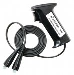
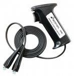
I use a remote starter switch like the one pictured below. This allows me to check my timing by myself. One lead goes to the 12volt battery cable ( Not the cable going to the starter itself) on the starter solenoid, and the other goes to the small terminal on the starter solenoid that has the Yellow or Yellow/Red wire attached to it. Caution: There is another small terminal on the starter solenoid, however, it is attached directly to ground and has a small black wire going to it. If you connect to this one, bad things may happen to your remote starter switch...LOL! Press the switch and the starter will engage. To stop the starter, release the switch.

Remote starter switch.jpg
 

Attachments

  • Remote starter switch.jpg
    Remote starter switch.jpg
    37.7 KB · Views: 0
Last edited:

scout-j-m

Chief Petty Officer
Joined
Jul 31, 2009
Messages
636
Good to hear on the interlock switch. That aligns with what I was able to find out as well. I just have to find where they have butt connectors or an end where I can connect the two with a jumper wire.I went ahead and did a quick compression test after posting last and got about 110 psi on all 3. At first I was like this thing's compression is terrible for a rebuild...but then saw where that is normal and it will climb significantly over the break in procedure. So I am not gonna fret over that and I will wait to check it again until the 10 hr break in is complete.
 

scout-j-m

Chief Petty Officer
Joined
Jul 31, 2009
Messages
636
Something else that popped into my mind after adjusting the throttle cam pick up point and WOT and that is in regards to the idle screw setting. I did not mess with it any since I took it off so the screw is already screwed in a ways to some previous idle adjustment. Prior to adjusting the pickup point and WOT setting should I have backed the idle screw all the way out so that the towershaft is completely closed against the block in that direction? Or is what I did ok? As it stands now, after I adjusted the pickup point so that cam was just touching the eccentric screw and then adjusted the cam rod (had to shorten it as carb was opened past full) to achieve a fully open carb at WOT, the cam backed off of touching the eccentric screw. Meaning the idle screw will need to be increased even more. I am just not sure it is a deal where both methods produce a similar result or if by doing it my way creates some sort of issue. The only issue I see is that if I were to repeat it with the idle screw backed off it would allow the throttle to open up more in neutral before hitting the stop on the gear shifter linkage near the throttle tower.
 

scout-j-m

Chief Petty Officer
Joined
Jul 31, 2009
Messages
636
I got the towershaft corrected I believe and reset the cranking WOT timing to 32 deg. I put the motor in a tub and started it up for the first time. Started easily and ran pretty good for a few minutes while I let it warm up and tinkered with the idle adjustment trying to get 1100 or so rpm's in neutral idle.

But then I ran into a problem...after it got good and warm it lost fire on cylinder one. I was using my new timing light, which has a tach, to monitor everything since my console tach still isn't working. I double checked with a spark checker and it confirmed it. I swapped the plug wires and it still was dead on cyl #1. So then I swapped the #1 and #2 coils. Upon startup I had spark on all 3 cylinders now, however, after letting it run a minute or so the spark to #1 died out again confirming that the coil is not the issue.

I am going to try to do a full ignition test someday this week. In the meantime what is likely the culprit since it seems to be failing when it gets hot? The switch box seems like it would be the component that would be affected by this but I just don't know. My trigger did have a small crack in it but otherwise seemed fine. I think during the last test I did on the stator prior to the rebuild it passed the voltage test and resistance test. Something screwing up when it gets hot seems like it will be very tricky to track down.

A side note: I mentioned above my new tach did not work. Well my rectifier/regulator is also new. So while I unplugged the gray tach wire to the wiring harness and plugged it directly into the stator yellow lead and ran the motor....nada. Tried the other yellow lead...nada again. Tested the yellow leads while the motor was running with my multimeter on 200ACV and saw like 0.1-3V. Based on this are my stator charging windings for sure bad? Is this linked to my loss of fire? I understand the concepts of the ignition system, but I do not see how a bad stator would cause a firing problem on a single cylinder.
 

pnwboat

Rear Admiral
Joined
Oct 8, 2007
Messages
4,251
You can double check by reversing the Red and Blue stator leads on the switch box. If the problem moves to a different cylinder, then it could be the stator. If no change, then most likely the switch box itself.

The motor needs to be running at a minimum of 2000 - 2500 RPM's before it'll begin to develop enough voltage to charge.
 

pnwboat

Rear Admiral
Joined
Oct 8, 2007
Messages
4,251
It just dawned on me that your stator is kind of unique in that it has a low speed winding and a high speed winding. You cannot reverse the stator leads on the switch box. My apologies for suggesting that without thinking about the low/high speed winding.

Based on what you've done so far, I would say that the switch box is the most likely culprit though. You can try some freeze spray available at electronics store and freeze the switch box after you loose the spark and see if that restores the spark to number 1 cylinder.
 

scout-j-m

Chief Petty Officer
Joined
Jul 31, 2009
Messages
636
Thanks pnwboat, you are always a huge help. I am leaning towards the switchbox as well because I don't really see how heat would affect the stator. I also know my switchbox wires have some melted rubber on them...looks to me like some of the insulation/filler in there melted and ran out along the wires. I will give the spray a try and continue to do testing on the ignition system. I should be able to at least for sure eliminate the trigger based on tests.

Do you have any input on the no charging voltage readings from my stator? If the charging aspect of it is bad, I would want to replace it anyways and could go ahead and do that to see if it fixes the firing issue.
 
Last edited:

pnwboat

Rear Admiral
Joined
Oct 8, 2007
Messages
4,251
As far as the charging issue, make sure the RPM's are high enough. You need to be at a minimum of 2000 - 2500 RPM's before the stator winding will generate the proper charging voltage. The resistance of the charge winding (two yellow wires) when disconnected is about .6 OHM's. Almost a short.

NOTE: Dry Ice (if it's readily available in your area) is another option to freeze the switch box. No messy water created when it melts. Just vapor which instantly evaporates, but it is very very cold. Use thick gloves or oven mitts to protect your hands.
 

scout-j-m

Chief Petty Officer
Joined
Jul 31, 2009
Messages
636
I didn't consider the rpm range. I was checking it at 1100 rpms. I can try that again at a higher range and report back if I get a change.
 

scout-j-m

Chief Petty Officer
Joined
Jul 31, 2009
Messages
636
Have you had a chance to check anything else yet? Any updates?

Not yet. In anticipation of likely having to buy a new stator, switchbox, and/or trigger I have been trying to put in a couple extra hours each day to get some OT to cover the cost.

I am going to check the stator charging output today though. I'm going to make sure I get the rpms up to see if I see any voltage on my multimeter. I am not confident I will though. When I hook the tach (essentially brand new) directly to each yellow stator wire it doesn't budge. I am also going to run it till that cylinder loses spark again and test the running voltages of the high and low speed stator leads at various rpms. According to the CDI Ignition guide the low speed DVA reading should be 180-400V and the high speed should be 25-100V.
 

scout-j-m

Chief Petty Officer
Joined
Jul 31, 2009
Messages
636
I have some results I am about to post. I was wondering though if I should be creating a new topic for this since my ignition problem is separate from the actual rebuild?
 

scout-j-m

Chief Petty Officer
Joined
Jul 31, 2009
Messages
636
I was able to go through most of the ignition system tests earlier today with the help of my dad. I followed the order laid out in my service manual.

Switch Box Stop Circuit Test
Manual says touch black/yellow switchbox wire to ground while cranking. Should see 200-360V DVA.
  • Cold cranking = 211V
  • Warm cranking = Did not attempt
Stator Output Test
Touching red lead to blue stator wire and black lead to ground checks the low speed while cranking. Touching the red lead to the red stator wire and the black lead to ground checks the high speed. Low speed should be 200V DVA minimum. High speed should be 20V DVA minimum.
  • Cold cranking low speed = 250V
  • Warm cranking low speed = Did not attempt
  • Cold cranking high speed = 26V
  • Warm cranking high speed = Did not attempt
Stator Resistance Test
Low speed is checked by placing one meter lead to the blue stator wire and the other lead to the red stator wire. Polarity does not matter. Low speed resistance should be 3600-4200 ohms. High speed should be 90-140 ohms.
  • Cold cranking low speed = 4000 ohms
  • Warm cranking low speed = 4200 ohms
  • Cold cranking high speed = 116 ohms
  • Warm cranking high speed = 112 ohms
Switch Box Bias Test
Connect the red lead to ground and the black lead to the white/black switch box terminal wire while cranking. Want to see 10-20V. Manual says less than 2V means a bad switchbox.
  • Cold cranking = 1.4V
  • Warm cranking = Did not attempt
Trigger Resistance Test
Disconnect all 4 trigger wires from the switchbox. Test the resistance between each of the 3 trigger sending wires and the trigger ground wire (black/white). Resistance should be 1100-1400 ohms for all three.
  • Cold cranking = 1330, 1300, & 1300 ohms
  • Warm cranking = Did not attempt
Stator Output Voltage Test (While Running)
Manual states to test the low and high speed voltage outputs while running between 1000-4000 rpms for ignition systems with erratic malfunctions. To test the low speed, probe the red lead to the blue stator wire and the black lead to ground while engine is running. Should see 200-330V DVA. For high speed, probe the red stator wire with the red lead and the black lead goes to ground. Should see 130-300V DVA.
  • Cold cranking low speed = 240V
  • Warm cranking low speed = 238V
  • Cold cranking high speed = 106V
  • Warm cranking high speed = Must have forgot to check
Stator Charging Wires Test
Tested the stator charging wires (both yellow) by connecting each to each lead of the multimeter. Manual says it should show 0.6-1.1 ohms. If it shows more replace stator. If it shows less I assume it also means replace stator. My meter?s smallest resistance setting is 200ohms so I?m not sure my results are accurate for the resistance test.
  • Cold results = 0.3-0.4 ohms
  • Warm results = 0.3-0.4 ohms
I also tested the AC voltage output of each lead with the motor running at around 2k rpms. My meter was set to 200V AC and I connected the red lead to the yellow wire and black to ground checking both stator wires.
  • Results = No real reading on either yellow wire. Maybe saw 0.1 or so volts but nothing significant
 

scout-j-m

Chief Petty Officer
Joined
Jul 31, 2009
Messages
636
So based on the failure of the running stator voltage test (low voltage on high speed winding) and failure of the stator charging winding voltage, the stator appears to be bad. The switch box is also bad based on the switch box bias test. Although, I am not sure the switch box test can be taken as accurate since the stator is bad. Does it look like is also bad or is the best bet to replace the stator and see if the switch box still fails that test?

Also, were my testing methods of the stator charging winding valid? And a related side note is that my previously non-working tach was showing sporadically showing a few hundred rpms with the stator charging leads disconnected but the recitifier still hooked up including the gray tach wire to the motor wiring harness. When I connected the yellow leads and restarted the motor the tach didn't budge from its off position of below zero. Not sure if this supports the results from the stator charging winding test or not.
 

scout-j-m

Chief Petty Officer
Joined
Jul 31, 2009
Messages
636
Also noticed a small amount of water weeping from the exhaust cover around the top and around a few bolts. What is the recommended torque for these? Cant remember exactly what I torqued them to. I snugged up all of the accessible ones about 1/3 of a turn and the leaking from the bolts seemed to stop although a little water was still coming from the top. Looked like a tiny tiny bit of water was getting in the cylinders but not enough to affect it running...at least prior to the top cylinder losing fire from my ignition problem.
 
Top