Missing wires in ignition system wiring harness (pics incl.)

scout-j-m

Chief Petty Officer
Joined
Jul 31, 2009
Messages
636
This post is in regards to my 1994 70HP Force.

I was doing some voltage and resistance testing on my ignition system over the weekend. While doing so, I noticed that the wiring harness butt connectors had two missing wires on the ignition/motor side. I'm not sure if it is clear to everyone in the picture but the wires with nothing plugged into their butt connectors are the purple one and tan/blue. The other connections are all there. Those wires include the gray tach wire from the rectifier, the red wire from the rectifier, the black/yellow stop switch wire, and two more thicker gauged red wires which go to and from the fuse above the coils.

Can anyone tell me what these missing wires are for and are they for something important. I couldn't find any mention of them in my Clymer manual wiring diagrams. Not sure if it matters or not but my motor has the thunderbolt ignition system.

0CE23EE1-0629-48C3-AE60-DB97F73FAF52_zpssck50alr.jpg

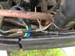
While hunting around for any unplugged wires, I found this brown/white wire also missing his female plug end. I know the green and blue wires seen in the picture are tilt/trim wires and the solid brown wire is the overheat buzzer. So I am stumped on this wire as well and would appreciate any help.

E222CEC1-EBCB-49CB-8D24-11420CE83D2F_zpswrhjl0lp.jpg

Finally, I just wanted to share this last picture. It is the wiring coming from the trigger directly below the flywheel. Having not yet pulled the flywheel to look at it in more detail and repair, it appears as if the purple wire (for cylinder 3 I believe) is bare and may almost be worn completely through. Also appears another wire or two may have been spliced together before by a previous owner. I plan to pull the flywheel this week and repair this and inspect everything under there since I have yet to pull the flywheel in the 6 or 7 years I have owned the boat.

9557C4CE-ADD2-49C8-8E67-58A1E695A37A_zpsqplnayum.jpg
 

Attachments

  • E222CEC1-EBCB-49CB-8D24-11420CE83D2F_zpswrhjl0lp.jpg
    E222CEC1-EBCB-49CB-8D24-11420CE83D2F_zpswrhjl0lp.jpg
    90.4 KB · Views: 0
  • E222CEC1-EBCB-49CB-8D24-11420CE83D2F_zpswrhjl0lp.jpg
    E222CEC1-EBCB-49CB-8D24-11420CE83D2F_zpswrhjl0lp.jpg
    90.4 KB · Views: 0

pnwboat

Rear Admiral
Joined
Oct 8, 2007
Messages
4,251
Those "extra" wires are probably far additional accessories like maybe a trim gauge etc. I would definitely take a closer look at those trigger wires.
 

scout-j-m

Chief Petty Officer
Joined
Jul 31, 2009
Messages
636
I was thinking the same. I'm assuming one of the 3 wires is at least a speedometer wire. I have the speedo tube coming out of my lower unit but it is zip tied out of the way and not connected to anything.

And I am going to make checking/fixing that trigger wire a priority. My reason for testing the ignition system was due to a generally poor running engine plus some big engine misses at medium to high speed throttle which feel like sporadically losing a cylinder. Seeing the frayed wires, I'm thinking that maybe the stator or flywheel is causing interference or that the frayed wire to cylinder 3 is shorting out.
 

pnwboat

Rear Admiral
Joined
Oct 8, 2007
Messages
4,251
Might want to consider replacing the trigger assy. if the trigger wires are badly damaged. The trigger assy. moves with the throttle to advance the timing as you increase throttle speed. Sometimes the wires rub against the block at certain throttle positions if not properly positioned.

http://www.ebay.com/itm/Trigger-fro...9A3-/121602129785?hash=item1c500d3f79&vxp=mtr

If that's not it, you can measure the stator resistance with an Ohm meter. If you have the Mercury style Switch Box ignition system, that year motor may have the type of stator that has a Low Speed winding and a High Speed winding. If the High Speed winding is bad, that would explain poor high speed performance.

Low Speed winding should read 3250 - 3650 Ohms. High Speed wind should be 75 - 90 Ohms.
 

scout-j-m

Chief Petty Officer
Joined
Jul 31, 2009
Messages
636
Might want to consider replacing the trigger assy. if the trigger wires are badly damaged. The trigger assy. moves with the throttle to advance the timing as you increase throttle speed. Sometimes the wires rub against the block at certain throttle positions if not properly positioned.

http://www.ebay.com/itm/Trigger-fro...9A3-/121602129785?hash=item1c500d3f79&vxp=mtr

If that's not it, you can measure the stator resistance with an Ohm meter. If you have the Mercury style Switch Box ignition system, that year motor may have the type of stator that has a Low Speed winding and a High Speed winding. If the High Speed winding is bad, that would explain poor high speed performance.

Low Speed winding should read 3250 - 3650 Ohms. High Speed wind should be 75 - 90 Ohms.

I checked the resistance of both that day. My low speed was something right around the lower range you listed...like maybe 3300-3400 ohms. Seems like my high speed was a higher than 90 though. I cant remember exactly, just that it was within the range listed in the manual.

The trigger resistance was within manual specs as well.

I'll fix the wiring and visually inspect everything to see if that helps.
 

jerryjerry05

Supreme Mariner
Joined
May 7, 2008
Messages
17,926
The "extra" wire are for Trim/tilt gauge .
Outboard ignition . com has test procedures for that motor.
Dropping a cylinder could be a bad trigger lead?
No speedo wire.
Compression test?
 

scout-j-m

Chief Petty Officer
Joined
Jul 31, 2009
Messages
636
The "extra" wire are for Trim/tilt gauge .
Outboard ignition . com has test procedures for that motor.
Dropping a cylinder could be a bad trigger lead?
No speedo wire.
Compression test?

I believe I have tested the entire ignition system although I need to go back at check the voltages again. I last did that a couple of weeks ago and dont remember if I performed absolutely every check. Also, my multimeter's lowest resistance setting is only 200 ohms so it was impossible to read the resistance on the coils since they are something like 0.5 ohms. By the way, I did all of this according to the clymer manual and a page I printed off from CDIelectronics.com.

The motor's compression aint too hot...110 psi on the top 2 and 90 on the bottom 1. I haven't used a different gauge to compare readings with but I have checked it 3 or 4 times and it has been consistent so I am at least confident the bottom cylinder is >10-15% different than than the others. I do need to do it again to ensure I do it correctly. I am not sure my past checks have been with the engine warm and with all plugs removed. Maybe I can find another gauge to borrow to try then as well.

I am going to pull the head soon to take a look, I was just trying eliminate any problem from the ignition system that could compound the compression problem. My plan was to statically check the ignition system, re-check fuel system from tank to carb, clean carb and replace all gaskets and replace any needles/jets/floats that are worn, statically check the timing, and then do a dynamic timing test. I will do the dynamic test on a calm evening at a small (600 or so acres) lake near my house which should make it easier.
 

jerryjerry05

Supreme Mariner
Joined
May 7, 2008
Messages
17,926
You can actually see in the cylinder with a small light.
Remove the plugs.
Even a long skinny screwdriver can tell you the condition of the cylinder walls.
Remove plugs.
Insert screwdriver in the hole turn flywheel until the driver stops going in.
Then try to rub the walls and see if it catches in any grooves.
Remember there are holes in there to allow fuel and air to enter/escape.
 

scout-j-m

Chief Petty Officer
Joined
Jul 31, 2009
Messages
636
You can actually see in the cylinder with a small light.
Remove the plugs.
Even a long skinny screwdriver can tell you the condition of the cylinder walls.
Remove plugs.
Insert screwdriver in the hole turn flywheel until the driver stops going in.
Then try to rub the walls and see if it catches in any grooves.
Remember there are holes in there to allow fuel and air to enter/escape.

Cool. I will give that a try first then.

I have been studying the forum pretty heavy the past few weeks and I plan to install new rings myself if it looks like that's what it needs.
 

jerryjerry05

Supreme Mariner
Joined
May 7, 2008
Messages
17,926
You decide to rebuild.
Take lots of pics along the way.
Will help when reinstalling.

Gosh!!! I wonder where these extra screws go???
 
Top