carb and tuning 115hp 1978

comet424

Petty Officer 1st Class
Joined
Jul 28, 2012
Messages
203
hi
I followed the carb tuning tutorial by Frank Acampora but had more questions for him,. Since emailing him on this site doesn't work, will not send personally to him, and on his video It keeps getting deleted if I post my email address.

but I followed the instructions could have gone in more detail.

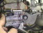
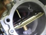
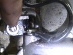
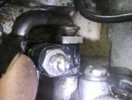
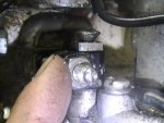
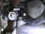
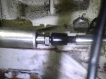
but I set the mark for the carb setting, and when I push all the way forward the throttle it wasn't all the way open so I adjusted the length of the adjuster bar so it be fully open, when I go back to center the Tick mark for the carb is below center is that ok??


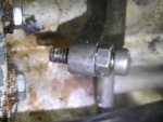
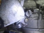
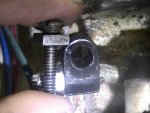
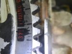
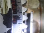
next is working on the static timing, I have the marks on the fly wheel lucky, but to ground the spark plugs do I just add a clamp to clamp the spark plugs to the ground somewhere? and that adjuster for the distributor is loose. So in full throttle I can move the bottom have a 1/4" or so back and forth is it supposed to be tight?
 

Frank Acampora

Supreme Mariner
Joined
Jan 19, 2007
Messages
12,004
AS I did mention in the vieo, the marks are simply a starting point. When set for WOT and fully opened butterflies, the mark(s) on the cam will most likely be below the black roller.
 

comet424

Petty Officer 1st Class
Joined
Jul 28, 2012
Messages
203
ok ya now about the loosen of the adjuster for the distrubtor? lots of play if ill try to post the pics
the idling screw is it set right?? as I cant test it . You cant get ears for this engine and a barrel is not wide enough for this engine so I gotta test it in the river.

but on the decal roughly 32 degrees on the decal, that's where its supposed to fire right??
I could use more detail u just press on the belt and its supposed to just fire ?? by just touching the belt.
 

comet424

Petty Officer 1st Class
Joined
Jul 28, 2012
Messages
203
No Title

so in the images youll see the set screw so what are you looking for when its idle and in gear? I figured just be idle in neutral?? why does it have to be in forward gear ?
as you can see the adjustment has a lot of play in it is that ok??

so ill look for clamps to clamp spark plugs to ground or if I ground the coil, and use the mulitmeter on the white white I seen, but doesn't help enough as I not sure what I looking for when you set that set screw
 

Attachments

  • photo204198.jpg
    photo204198.jpg
    47.8 KB · Views: 0
  • photo204199.jpg
    photo204199.jpg
    42.8 KB · Views: 0
  • photo204200.jpg
    photo204200.jpg
    65.5 KB · Views: 0
  • photo204201.jpg
    photo204201.jpg
    67.5 KB · Views: 0
  • photo204202.jpg
    photo204202.jpg
    43.6 KB · Views: 0

comet424

Petty Officer 1st Class
Joined
Jul 28, 2012
Messages
203
No Title

also setting this Float screw whats that?? and the adjustment for the throttle or idle screw whatever you call it, should both carbs be exactly set the same number of turns as mine arent
 

Attachments

  • photo204198.jpg
    photo204198.jpg
    47.8 KB · Views: 0
  • photo204202.jpg
    photo204202.jpg
    43.6 KB · Views: 0
  • photo204203.jpg
    photo204203.jpg
    52.4 KB · Views: 0
  • photo204204.jpg
    photo204204.jpg
    51.9 KB · Views: 0
  • photo204205.jpg
    photo204205.jpg
    47.9 KB · Views: 0

comet424

Petty Officer 1st Class
Joined
Jul 28, 2012
Messages
203
I tightened up that screw you see in pic going up and down it tightens into the distrubtor seems to have taken the play out I not sure how tight so its slightly tight but gonna test for this static timing now
 

comet424

Petty Officer 1st Class
Joined
Jul 28, 2012
Messages
203
No Title

ok so I think I got it, here some pics I don't think I need to adjust the adjuster I snugged up that top screw holding the plastic part down

so I turned the engine I guess its the 36 Degree mark you set it to I noticed, so its just where the 13 volts drops to .01 volts and when I press on the belt on the left side where you make the adjustments it jumps it to 13 volts, but if I press on the belt on the other side nothing. so is it set correctly??

and how I getting the 13 volts is

I run a 12 gauge wire from the ignition coil to ground, I run multi meter black to ground and I run the postivie lead to the white black wire off the distrubtor

so is that correctly set now?
here some pics
 

Attachments

  • photo204208.jpg
    photo204208.jpg
    56.7 KB · Views: 0
  • photo204209.jpg
    photo204209.jpg
    46.4 KB · Views: 0
  • photo204210.jpg
    photo204210.jpg
    59.1 KB · Views: 0

comet424

Petty Officer 1st Class
Joined
Jul 28, 2012
Messages
203
if that all correct how do I make sure the carbs are set both right for there needle valves? hopefully I can test it with water by this weekend or so maybe sooner if I can get the boat in the water to test it
 

comet424

Petty Officer 1st Class
Joined
Jul 28, 2012
Messages
203
No Title

oh another question the throttle cable doesn't go back into the locking table on that tower, I can pull it there is spring loaded at the end to line up the cable to get it to lock down,

or do you un screw the end and adjust it till its a regular easy fit ??

here some pics
 

Attachments

  • photo204211.jpg
    photo204211.jpg
    59.1 KB · Views: 0
  • photo204212.jpg
    photo204212.jpg
    47.5 KB · Views: 0

comet424

Petty Officer 1st Class
Joined
Jul 28, 2012
Messages
203
I guessing that is normal to have the tension on there I guess that's for forward and reverse so It can slide back and forth

but I guess its all set just need help if I did that static timing right?? how to set the needle valves right for both carbs
 

Frank Acampora

Supreme Mariner
Joined
Jan 19, 2007
Messages
12,004
The throttle cable should have about 1/4 inch pulled out of the large spring loaded fitting. This allows the engine to positively shift into gear before the throttle advances. You set the spring loaded fitting approximately correct. Then you advance the throttle a bit and set the control cable into the clamp. Once the clamp screw is tight, you clip the fitting over the ball post and then pull the control handle back to neutral.

Timing is either 32 degrees BTDC or 30 degrees BTDC. Your distributor does not have the correct screw and it appears that there may be some slop. You definitely need to find the correct shoulder screw.

One of your photos shows the idle stop screw with a locking nut. This screw is used to adjust the idle speed.

Carb low speed needles are set to the same setting--usually 1 to 1 1/4 turns out from lightly seated will be about right.
 

MickLovin

Master Chief Petty Officer
Joined
Feb 18, 2013
Messages
822
You need to set your timing @ 32 or 30 degrees, with no slop in that shoulder screw, also check your TDC to ensure your distributor marks match up to the flywheel, if that is ok then set your 32 or 30 degrees BTDC, it is also advisable to check your tension on your distributor belt, it should flex to a 1/4 inch with a .008 feeler gauge more than 1/4 inch is too loose and less than 3/16 is too tight. The distance on the distributor timing adjuster is approximately 5/8 inch but this varies on different HP rated motors. By pressing the belt you should either go from 0 volts to 12 or 12 volts to 0 when a voltmeter is across the two terminals on the distributor positive lead on the right terminal negative on the left.
All said and done Frank is the Guru.
 

comet424

Petty Officer 1st Class
Joined
Jul 28, 2012
Messages
203
ah ok ill double check I took a pic before I removed the fly wheel on the decal its set to the first tick mark, and the distributor T mark was pointing in the middle the teeth, on the fly wheel. So that's how I re set it back up.
ill double check the belt tension

I looked on boats net at the image it looks like a bolt they use to clean up the slop, and doesn't show that flat square piece of metal that's under that screw head, Ididnt take it out but looks like just a regular screw someone used. Shouldn't it be a nut and bolt? ill re look later today, I did tighten the screw and it took the play away.

and I didn't use the multiple meter, Blue for Postive and Blackwhite wire to the black lead of the multimeter. and when I set it to mark I showed in the picture on the decal I guessing that's 36 or is that actually 32? can you guys verify from that decal sticker??

but ya if I press on the right side she will jump and I hear the coil crackly when I press on the belt.


and ok ill turn both carbs in and turn them both exactly same out then, I know I had set that last year off set a little the one as it wasn't running right, but now with the carbs set better now then it should all work well


oh and what are you guys using to test this engine in water, since there are no ears made for this and you cant get this in a barrel did you guys build a special box to drop the lower end in and filled it with water?


thanks for the help so far I appreciate it very much guys
 

comet424

Petty Officer 1st Class
Joined
Jul 28, 2012
Messages
203
oh forgot to ask again, but is that idle screw set right? or probably because the carbs set wrong? I did turn them in and I turned them 1 turn out, I did notice they don't match the threadings as they don't line up exactly the same but turned both out 1 full turn

but the question is when in the water and you say idle forward? what should the engine be doing to set that screw in the proper position? just above stalling or something?
 

comet424

Petty Officer 1st Class
Joined
Jul 28, 2012
Messages
203
apparently its a swivel lever its called I don't have that washer but its plan it looks but who has replaced this?? what kinda size bolt is this or screw whatever you wanna call it as I cant find specs
 

Frank Acampora

Supreme Mariner
Joined
Jan 19, 2007
Messages
12,004
Every carb is different and yes, the slot in the screw will be in a different position at one turn out. There is no right or wrong to set the idle stop screw. You use it to adjust the idle to 750 RPM in the water in forward gear. Too low and the engine will stall in gear at idle. Too high and it will crash loudly when put into gear. Set the idle so that the engine just "clunks when put into gear.

The screw on the distributor is incorrect and it has a plain flat square nut on it. As I said, you need to find a shoulder screw for there. This same part was used on almost all Chrysler and Force engines. There is no bushing inside the plastic block. HOWEVER, If you can make a bushing, you can use the regular screw until you find the correct part.

Since you apparently have a 2 piece lower unit with a thrust pin prop, you take a regular set of muffs and cut some rubber off the top and bottom. Then they will fit over the water intake with little leaking.
 
Last edited:

comet424

Petty Officer 1st Class
Joined
Jul 28, 2012
Messages
203
oh ok the reason I said a bushing on this link as I googled this bolt
it shows a bushing
http://www.ebay.co.uk/itm/F85026-F3...g-1989-Force-35-HP-Model-357F9A-/220974659491

so wasn't sure the marina has an old one off a scrap engine for 20 dollars ill just get it just expensive.


as for the idle set screw so on the shifter I just push it a tiny bit forward and that's the being in gear and then I adjust the set screw right?

I figured it would have been just idle


ya I have the prop with the pin but I don't have the Cone, and the one guy was selling it for 110 dollars for just the cone and I needed the other plastic spacer too

so I was thinking I just put some red lock tight on the thread and tighten the nyon nut on using a washer and a castle spacer to press against the prop.


so going to get the screw later today
 

comet424

Petty Officer 1st Class
Joined
Jul 28, 2012
Messages
203
No Title

ok so I was able to get the screw and used the same settings they had but from the decal can you tell me where the 36 degree mark is or is it supposed to fire on the 32 degree mark??

the first pic shows sitting on 32 mark or least that's where I guess from the decal

2nd pic I moved it and you can press on the belt on the back side (right side) and it will got to 12 volts

third pick I adjusted more it sits powered up at 12 volts and if I press on the belt on the left side it drops to 0

so can you break down exactly what I need to be precise with this setup detailed if possible what I looking for achiving etc
 

Attachments

  • photo204375.jpg
    photo204375.jpg
    43.4 KB · Views: 0
  • photo204376.jpg
    photo204376.jpg
    45.1 KB · Views: 0
  • photo204377.jpg
    photo204377.jpg
    41.6 KB · Views: 0
Top