Force 150 head gasket questions

HotTommy

Lieutenant Junior Grade
Joined
Mar 15, 2013
Messages
1,025
I recently purchased a 1993 Force by Mercury 150 HP two cycle outboard engine. it was not running and was partially disassembled when I got it. The seller claimed it ran well until his last salt water outing when it began to miss on the way home. He pulled the head in an attempt to diagnose the problem and found the top piston badly pitted as in the photo that follows. He suspected detonation due to a lean carburetor. I'm not taking his word as I try to figure out what I'm working with.
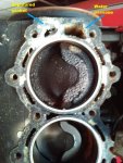
cylinder.jpg

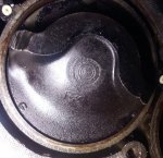
My questions regard the likely cause of the piston damage and some head erosion I will describe. In the photo I have marked the "water passage" where water was intended to flow between the head and the block. Just to the left is an area I labeled "ruptured gasket." There is a water passage on the block side of the "ruptured gasket" area, but there is no corresponding passage on the head side. it appears that the gasket was intended to shield the head from the water flow in that area. But, the gasket is ruptured and a hole as wide as the rupture and up to 1/16" deep has been eroded into the aluminum head. The eroded hole had gotten close enough to the cylinder to make me suspect water was able to find its way past the gasket into the cylinder. If that were the case, would that be a likely cause for the piston damage?

i took the head to a good machine shop to be resurfaced. Resurfacing reduced the width of the eroded hole and it looks to me that there is enough space around the cylinder for a good head gasket seal. However, a small amount of the eroded hole remains. I am concerned that the hole will allow the gasket to deform there and encourage water to once again rupture the gasket. So my next question is whether there is a suitable way to fill the small eroded hole just to provide the gasket a firm surface on which to rest?

My final question is more out of curiosity than anything else. I'm wondering if the exposed surface of the head gasket was supposed to be strong enough to stand up to the force of the hot water rushing by it. Somehow I don't find it surprising that a gasket would fail under these circumstances. Therefore, I'm wondering if my attempt to fix this is even worth the effort. So my question is, is this kind of gasket failure common or uncommon? Or am I completely misunderstanding what has happened. I welcome your insight and comments.
 

pnwboat

Rear Admiral
Joined
Oct 8, 2007
Messages
4,251
Re: Force 150 head gasket questions

Most common cause for the piston damage is fuel mixture to lean, or timing too far advanced. It's pretty common. Quite a few things can cause a lean condition. Carb float level not set right, debris in the carb, bad fuel pump diaphragm...in your case, you should have two fuel pumps in series, lack of an inline fuel filter between the fuel pumps and carburetors. Seeing how only 1 piston was damaged, most likely lean fuel mixture on the top carburetor. I've not seen water in a cylinder cause that type of damage...but I'm not an expert in that area. That type of piston damage is usually the result of excessively high temperature. I don't think water in the cylinder will cause that. If enough water gets in there, it may affect the spark, or score the cylinder walls, possibly hydro-lock the motor etc. but it won't cause the pitting that you see on the piston. I don't think that eroded hole goes anywhere. Like you mentioned, there is no corresponding hole in the head, so I'm not sure I would worry too much about it. If you feel that it may be a problem, I've seen several 150HP heads on E-Bay for a reasonable price, and a few that were way out of line too!
 
Last edited:

Frank Acampora

Supreme Mariner
Joined
Jan 19, 2007
Messages
12,004
Re: Force 150 head gasket questions

That is classic detonation damage due to lean running. You will see the same pock marks in the combustion chamber. It is difficult to tell from the photo, but if the piston rings did not break OR if the bore is not scored, a simple piston replacement will suffice. HOWEVER: You need to check the carbs, paying special attention to the top carb.

If it is dirty or partially clogged, or even if the low speed needle was set too lean, this will cause detonation at or near full throttle and sometimes at partial throttle.

Since these carbs have no vacuum enrichment circuit and since the low speed circuit enters the carb behind the butterfly, it is always at manifold vacuum and always delivers fuel. Thus, setting it too lean will also lean the mixture at higher throttle settings.

Disassemble the carb and clean well. Remove the low speed needle and ream the passage with a pipe cleaner and WD40. clean the small diameter brass tube the same way with either a small pipe cleaner or very small diameter copper wire. Depending upon carb model number there will be either a large hole or several small holes in the top of the carb casting right near the butterfly. Clean these well OR remove the welsh plug at the top of the carb and clean the whole chamber.

Gasket and head: The gasket is blanked off where you show a perforation and this is simply because there is one less knife to fabricate on the die cutter and a hole is not needed there. Most gaskets will show some degree of bending inward toward the head from water pressure and some will perforate. Water will collect there and erode or corrode the head.

Water flow is: Water exits from the exhaust chest and travels around the block, cooling the cylinders. Then at the top, it passes into the head and through the thermostat to travel downward, cooling the head and exiting into the midleg.

The head is cast with as much open space as possible to eliminate cost and weight. You can simply clean the damaged area well to get a good grip and fill the hole with JB epoxy. If you are really worried, make an aluminum plate to the shape of the hole, partially fill the hole with epoxy, and top off with the plate. Then file flush

Getting back to the bad piston: If the cylinder is in good shape, the piston can be replaced without dismantling the engine. You remove the top carb, manifold, and reeds, and remove the rod big end cap through the opening. Then you push out the old piston and rod assembly. Be certain to retrieve and account for all 16 rollers and the two half cages.

Reassembling takes a good bit more time but is not too difficult. I have done this a number of times on 3,4, and 5 cylinder Force engines.

The fuel pumps are in series with the bottom one feeding the top. Put a cheap paper fuel filter BETWEEN the top pump and carbs. Failure of one pump will cause loss of performance so replace BOTH diaphragms and gaskets now, as routine maintenance.
 
Last edited:

HotTommy

Lieutenant Junior Grade
Joined
Mar 15, 2013
Messages
1,025
Re: Force 150 head gasket questions

Thanks for the thorough and excellent advice. I expected no less from you guys. .... I'll be back when I have my next question.
 

Frank Acampora

Supreme Mariner
Joined
Jan 19, 2007
Messages
12,004
Re: Force 150 head gasket questions

Oh, yes, I forgot to ask: How much did the machine shop mill the head? If they removed more than .030, compression may be high enough to require premium fuel. After you reassemble the engine test compression. If it is SIGNIFICANTLY over 150 PSI, then consider using premium.
 

HotTommy

Lieutenant Junior Grade
Joined
Mar 15, 2013
Messages
1,025
Re: Force 150 head gasket questions

If I make it that far I will. I'm starting a new thread now on a different question.

Edit: I'll hold off on that new thread a bit. I think I found my answer on someone else's thread.
 
Last edited:

Frank Acampora

Supreme Mariner
Joined
Jan 19, 2007
Messages
12,004
Re: Force 150 head gasket questions

A scored cylinder, depending upon the severity of the scoring, CAN deliver decent compression. Generally speaking, if there is a single line or two that is not too deep you should not need to overbore, a simple honing should do.

However, if you can catch a fingernail in the score mark, it is probably .005 or deeper and you would need to overbore.

Unfortunately, to accurately measure you need a special inside micrometer.

If you post a couple of good close shots of the cylinder, it might be possible to give an evaluation as to whether or not you could get away with honing.

Understand though that Chrysler (and probably Force) used a wear, out of round, or tapered tolerance of only .002 where OMC and Merc (I think) used .005 thus, you probably do have a little wiggle room

Also understand that by not boring, you may see a reduction in performance, even with a new piston and rings. For example if all other cylinders are about 145-150 and the bad cylinder is at about 120, obviously you will lose a couple of horsepower and probably a couple of MPH top end.

Also: Understand that in these engines even a .030 overbore give so little cubic inch gain that boring one cylinder is quite acceptable. The engine will never notice it. Generally, if I need to bore 2 or more, I bore all cylinders oversized and then for all practical purposes I have a new engine.
 
Last edited:

Faztbullet

Supreme Mariner
Joined
Mar 2, 2008
Messages
15,616
Re: Force 150 head gasket questions

Watch milloing down the head as to much will cause piston to hit in top of cylinder. Also milling head on crossflow results in very little compression increase, like a Johnrude you close the cc's the combustion area to increase compression.
 

HotTommy

Lieutenant Junior Grade
Joined
Mar 15, 2013
Messages
1,025
Re: Force 150 head gasket questions

Thanks again. My plan is to remove the bad piston, hone the cylinder and then evaluate (with photos). Unless there is an overriding reason to do more to the cylinder, I'll put in a new piston, rings, and bearings, put everything back together and then check the compression.

I was checking out the connecting rod through the reed valve window earlier today. I'll be searching this site for advice on how to best handle the bearings during the swap. If anyone knows of a particularly good description, please point me toward it.
 

HotTommy

Lieutenant Junior Grade
Joined
Mar 15, 2013
Messages
1,025
Update

Update

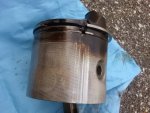
I removed the damaged piston today and I am extremely proud to announce that I am in possession of all 16 bearings! Next step is honing the cylinder a little to get a better picture of the score lines. Here's a picture of the side of the damaged piston. It appears one of the rings was broken near the area that scored the cylinder.

Piston.jpg
 

Frank Acampora

Supreme Mariner
Joined
Jan 19, 2007
Messages
12,004
Re: Update

Re: Update

Is that the same piston as in the photos in your original post? The first photo sure looked like detonation but a busted ring piece rattling around inside the combustion chamber would give the same look.

Your photo is typical: A ring breaks and pushes up through the top ring land, destroying the piston and damaging the cylinder. Yet, the piston skirt shows very little damage. There is hope, I have replaced pistons damaged just like this in my 150. The cylinders were lightly scored and honing was sufficient.

However, my advice about disassembling, inspecting, and cleaning the carbs still stands.
 

Jiggz

Captain
Joined
Oct 23, 2009
Messages
3,817
Re: Force 150 head gasket questions

I had the same problem with my '89-125HP almost two years ago and with the help of Frank and this forum I was able to repair it for under $200, which includes buying all the tools, i.e. honing kit, piston ring compressor, etc. I replaced the piston with Wiseco including the wrist pin bearing kit. One thing that will help prevent the same problem in the future is to chamfer the ports to prevent the ring from catching. I did this using a dremel tool and a small grinding stone.
 

HotTommy

Lieutenant Junior Grade
Joined
Mar 15, 2013
Messages
1,025
Re: Force 150 head gasket questions

Yes, that is the same piston. I picked up a hone this afternoon. I already have kits to rebuild the carbs and fuel pumps. I'll replace the fuel lines and install a fresh filter while I'm at it.
 

HotTommy

Lieutenant Junior Grade
Joined
Mar 15, 2013
Messages
1,025
After honing the cylinder

After honing the cylinder

I have some photos to share, progress to report and questions to ask. Here goes.

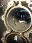
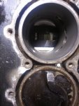
I honed the scored cylinder this morning and I'm encouraged by the results. The score lines are still visible and I can feel them with my fingertip, but they are too shallow to catch my fingernail. They don't look too bad to my eyes. The first photo shows the scores from an angle so they show well. The second photo shows them from almost perpendicular in an attempt to give you a sense of how deep they are.

score1.jpg

score2.jpg

It is apparent that the damaged ring caught the edge of the port near the score. As was suggested to me earlier in this thread, I'll chamfer the ports to minimize that as a cause for future problems. ... Unless I hear strong objections from those far more experienced than me, my plan is to do nothing more to the cylinder than chamfering the ports. I'll buy a new piston kit and attempt to install it. That brings me to my next two questions. ... Here's a picture of one of the undamaged pistons.

pistonb3.jpg

I post this because I need to know what size piston to buy. Does the "B3" stamped on the piston tell me anything, and what is the best way for me to know what size piston to get?

My final question is one I won't need answered for a while, but its bugging me just the same. I want to know if there is a best way to install the cage, bearings and connecting rod cap when the time comes. For example, is it better if the crank is closer or farther away from the reed valve window? Do you put the bearings on the piston half of the rod before or after you slide the piston into the cylinder? You get the idea. What seems to work best?
 

pnwboat

Rear Admiral
Joined
Oct 8, 2007
Messages
4,251
Re: Force 150 head gasket questions

Need to measure the cylinder bore with a telescoping snap gauge and a micrometer. That's the best way to do it. Otherwise you're just guessing at what the numbers on the pistons mean.

You could also measure the piston itself, however, they're not perfectly round to compensate for thermal expansion and different thickness between the thin wall of the piston and thicker area where the pin bosses are located.

Either way of measuring will get you in the ball park and is more reliable at "guessing" what the stamped numbers on the pistons mean.

Use some grease to hold the bearings in place. Regular bearing grease is not the best. Google "automatic transmission assembly grease". This grease is more compatible with the 2-stoke oil.

Forgot to mention one thing. The caps are "cracked" to separate them from the body of the rod when manufactured. This creates more surface area to hold the rod cap in place when bolted together. Each rod has a small machined area at the parting line. This is used to insure the cap is properly aligned before tightening the rod cap bolts. If the cap is properly aligned, you should not be able to feel the parting line if you take you finger nail or other sharp object and drag it across the parting line. If you can feel a lip at the parting line, then the cap is not aligned. This lip that you feel on the machined area on the outside of the rod, will also be present on the inner circumference of the bearing surface of the rod. You can imagine the needle bearings rolling over a lip. Not a good situation. If you tighten the rod bolts with the cap mis-aligned, if messes up the mating surface of the cap and rod body making it very very difficult to get them aligned again.

Put some grease on the crank pin. I rotate the crank pin so that it is closest to the opening. Seems to work best for me. Install the piston/rod and bring the rod very close to the crank pin. Close enough to just allow sliding the cage assy. w/needle bearing in. Push one needle bearing in, then position the next bearing and push it in. Keep pushing the cage assy. w/bearings in, should be 8 of then for that half of the rod, until you see the cage assy. w/bearings start coming out of the other side of the rod/crank pin. Grease the bearing surface of the rod cap and stick the other 8 needle bearings and cage on it. Carefully place the rod cap on. Install the rod bolts but do not tighten all the way down. Position the rod cap checking for alignment of the parting line on the machined surface of the rod. Then tighten down and check parting line alignment again. I usually use some lock tite on the rod bolts. Red or blue, which ever you prefer.
 
Last edited:

Jiggz

Captain
Joined
Oct 23, 2009
Messages
3,817
Re: Force 150 head gasket questions

PNW covered it all. It is basically the same process I used except I started with the crank closes to the cylinder. Using a 1/8 or even 3/16 X 18 inch wire rod (I got one from those reflectors you used to mark the driveway) inserted from the reed side, I aligned the rod cap (from piston rod side) while pushing down on the piston into the cylinder to the crank pin. This ensures the rod cap rides the crank pin. After this without removing anything, I will continue to push in the piston until the crank pin is now close to the reed side. Then inserting the bottom cap into the alignment rod, I can easily place it next to the crank pin using needle nose pliers. And then the next step is to insert the first cap bolt but not tighten yet. This is just to hold the cap in place. Next remove the wire alignment tool and replace with the other bolt. Now push in the bottom cap to make sure it is properly aligned. Check with a small inspection mirror before finally tightening the cap bolts. In my case, I used triple guard grease to hold the bearings in place. So far it is still working after almost two years.
 

HotTommy

Lieutenant Junior Grade
Joined
Mar 15, 2013
Messages
1,025
Re: Force 150 head gasket questions

Great advice. I appreciate all of it. .... I fabricated a bore gauge out of two pieces of 1/4" threaded rod and a connector that allowed me to adjust its length. The cylinder appeared evenly round and with the original stock bore. This seems to confirm what the seller told me - that the engine had less than 200 hours on it. It also tells me I need the stock 3.375" bore piston kit.
 

Frank Acampora

Supreme Mariner
Joined
Jan 19, 2007
Messages
12,004
Re: Force 150 head gasket questions

If you don't have the tools, measure the bore with a good accurate ruler. It is 3 3/8 diameter if stock. IF the B3 means a .030 overbore, then the bore will be 3 3/8 plus almost 1/32 or very close to 3 13/32.

The reason for cracked cap rod technology is not for increased surface area.. If you look and an OMC rod, it will have two holes drilled through the rod at the break, actually decreasing the surface area. The rod ends are actually the outer race of a bearing with the crankpin and rollers being the inner race and rollers. All these parts are hardened all the way. Because of this, when the big ends are broken, while the mating surfaces may be irregular, at the bearing surface they form a very clean line--one that if properly aligned will be invisible to the roller(s) passing over it.

The need to break the rod cap is the reason for the vee notches on one side of the rod. That is how the rod is broken, by staking it there, while the flat notches on the other side of the rod are for lubrication.

That single score mark sure looks like it will hone out or mostly so. I think a simple piston replacement is the next step to try.
 
Last edited:

HotTommy

Lieutenant Junior Grade
Joined
Mar 15, 2013
Messages
1,025
A question while I'm waiting

A question while I'm waiting

I'll be waiting on parts for the next few days. In the meantime i visited the Wiseco Piston site and read their recommendation for breaking in an engine with new pistons. I highlighted the time requirements.

Engine Oil & Fuel
? Double the oil quantity with an approved TCW-3 oil.
? Use 91 to 94 octane premium fuel.
? Avoid products that have alcohol additives, or chemicals that may alter the fuel condition.


Initial Break-in & Warm-up
Allow four hours for break-in of a new piston and/or rings at idle speed only. For first 10 hours, avoid continuous
full throttle. Liquid cooled engines require that the engine be brought to normal operation temperatures to avoid
cold seizure that results from the piston expanding faster than the cylinder liner (which is being liquid cooled).
RPM Guidelines
? For the fifth hour and a half after warm up, operate the engine in gear approximately 1,500 RPM for the first
twenty minutes
.
? For the remaining forty minutes, operate the engine in gear no more than three thousand RPM.
? Use only enough throttle to plane the boat, then immediately throttle back to less than three thousand RPM.
? For the sixth hour, accelerate enough to bring the boat up on plane quickly, and bring the throttle back to
maintain the boat up on plane. During this period, vary your engine speed by accelerating to three fourths
throttle for a minute or two, then back to minimum planning speed.

I can live with that if it is truly necessary. But I suspect they may be minimizing their liability over an occasional part failure at the customer's expense. In other words, if they make the break-in procedure so onerous that hardly anyone does it, they can blame any failure on the customer rather than the part. What say you?
 

Frank Acampora

Supreme Mariner
Joined
Jan 19, 2007
Messages
12,004
Re: A question while I'm waiting

Re: A question while I'm waiting

In my engines, I exclusively use Wiseco pistons. After a rebuild, the first thing that happens on the water is a VERY BRIEF run at full throttle to check timing. Then, I run about two portable tanks at (25-1) double oil through it, avoiding full throttle but varying speeds. After that, I go to regular 50-1 and use full throttle, but avoid long periods of full throttle running for another couple of hours. AND, I never use premium fuel.

Remember: Wiseco pistons are used in a LOT of racing applications and they do recommend increased piston to cylinder wall clearance in modified engines. So their break-in probably reflects this extreme use.
 
Top