Force 125 Electrical Troubleshooting

rcracerx

Seaman
Joined
Nov 29, 2008
Messages
58
Hi guys I am new here finding this forum on Google after looking for information on a new "Project" I got myself into. I picked up a 85 19ft Bayliner BR with the Force 125 engine in pretty rough shape. I can see it needs a new deck and the interior is pretty beat up. Before I decide to take on this project I need to get the motor running and check its condition otherwise the whole thing is scrap.

The guy I got the boat from said that it has not been in the water in 2 years but he had it started earlier this year in the yard with muffs on. When I went to look at it he couldnt get it started because there seems to be a problem with the electrical system. The motor wouldnt do anything when he turned the key. The battery was good and had a full charge. We checked the obvious things like proper battery connections and he looked at some fuses. Everything appeared to be as it should be. He mentioned that he seems to remember replacing the ignition/key switch a few years ago when he had a similiar problem and that is probably what has happened again? Sound possible or more like bull? How can I troubleshoot this switch?

I have a test light and a voltmeter but I am not sure what I am looking for. I have wrenched on some cars in my day but never boats. Is there a way to "jump" the motor so to speak and bypass the switch like on the old fords? This way I could atleast make sure the engine runs before I move on with this project.

Another question if you dont mind. The very bottom of the motor below the propellor has been repaired. I am not sure what the part is called I think the "skeg"? It appears that at one time he must have hit something because the prop is new and there is a repair at the very bottom portion of the engine casting. He said it had been that way for years and it never caused a problem. Is this a serious problem?

I have ordered a manual for this engine online but it will be a few days before it arrives and I was hoping to get this motor running this weekend.

Thanks in advance for your time.

Rc
 

timdan94

Chief Petty Officer
Joined
Jun 23, 2008
Messages
480
Re: Force 125 Electrical Troubleshooting

I'd check the starter solenoid
 

rcracerx

Seaman
Joined
Nov 29, 2008
Messages
58
Re: Force 125 Electrical Troubleshooting

I'd check the starter solenoid

Thanks for your reply.

Do you know the procedure to check the solenoid?
Does the solenoid get power before the ignition switch? If so does that mean I can jump the solenoid without the key switch to turn the motor over? Will I have full ignition (spark) doing it this way? How would I shut the engine down if I started it this way?

Thanks
Rc
 

timdan94

Chief Petty Officer
Joined
Jun 23, 2008
Messages
480
Re: Force 125 Electrical Troubleshooting

When you turn the key without pushing it in do you hear the solenoid click?
If you don't I'd take a multimeter and see if you have power when the key is turned to the start position. If you don't I'd start looking to see if you have power to the key switch. If you do and you don't have power on the start contact on the switch I'd say it is the switch again. I'd also check the circuit breaker that is on the motor. I'd also check for other blown fuses. Oh and if its like mine make sure the little knob on the control is pulled out meaning that the motor is in neutral. Sometimes mine doesn't fully pull out and it is still in gear and won't do anything.
 

Frank Acampora

Supreme Mariner
Joined
Jan 19, 2007
Messages
12,004
Re: Force 125 Electrical Troubleshooting

Strange---Every engine I have ever bought was described as working when it was stored. Seems to be a common description. Last engine I bought with that description had a starter that would not turn, a solenoid that would not close, wiring that was melted, and jury-rigged wiring on the CD boxes--didn't even bother to test them.

In the front of the engine under the hood where the battery wires come in there will be a black solenoid. There will be a wire from the battery to the front of the starter solenoid and a red wire to the starter motor on the other side of the solenoid. Take a couple of screwdrivers or a short length of wire and jump from the battery (front) terminal to the small terminal with the yellow wire attached. With the key off, this will crank the engine with no spark. If the solenoid does not click closed, it is bad. If it does click closed and the starter motor does not turn, then the starter is bad. If both are good, then the ignition switch is bad.
 

rcracerx

Seaman
Joined
Nov 29, 2008
Messages
58
Re: Force 125 Electrical Troubleshooting

Great, thanks alot. That is exactly what I was looking for. I am going to get out there on Sat and see if I can figure out whats going on and this will help.

I will let you guys know what happens, and I am sure I will have a few more questions by then. :)

Thanks
Rc
 

rcracerx

Seaman
Joined
Nov 29, 2008
Messages
58
Re: Force 125 Electrical Troubleshooting

Update*

Okay I started tracing wires today and checking various circuits. The 12v acc panel was all screwed up but I think I got that straight now. Also I have the power trim up/down working now.

I tested the "B" terminal on the ignition switch for power and it was dead. I followed the wire back to the motor and ended up finding it on a BusBar. This BusBar powers the choke and various other components. The problem seems to be that I have no power going to that BusBar. I followed the battery cable into the motor and I have power there. The starter solenoid has power, but the wire that runs up to power the BusBar goes through a 12VDC25A circuit breaker. I have power to the incoming terminal of the breaker but no power on the output side to the BusBar. There is a small reset button on the top of the breaker that was up, I pushed it down but I still do not have power on the output side.

Can I assume that I need a new breaker? Where do I buy this part at? I checked BoatersWorld and West Marine here local and they had breakers but none that matched mine.

What could have caused that breaker to go?

Thanks for your time.

Rc
 

Frank Acampora

Supreme Mariner
Joined
Jan 19, 2007
Messages
12,004
Re: Force 125 Electrical Troubleshooting

As with Chrysler engines, Force used a LOT of standard parts.

If the breaker you are talking about is the one inside the engine on the bottom of the terminal bar, you can buy an equivalent at auto stores--however, it may be the metal case with no reset button. I know I have seen them in CarQuest and you can probably get them at NAPA and Pep Boys. The one without a reset will reset when it cools. As long as it is 25-30 amps and mounts the same it will work.

Before you buy a new one though, jump the two terminals to double check that voltage is not passing through it. The inside contacts are copper and the case is not water tight. You know what happens to copper in the presence of water.

As far as the skeg: It is always a positive if the skeg is the original one but the lower unit is under the water where the pilot can not see. Skeg repair is very common. You even see guys breaking them at the ramp when they drop the boat off the trailer---Yes, it does happen, and some people pay money to see a show like that. You only need to check that the gearcase was not cracked when the skeg broke and that the welding of the skeg repair is sound and of good quality.

On that 140 in the avatar, I broke a skeg and sent the case to a welding school to have it repaired for nothing. Well! You get what you pay for. They got the skeg on tilted from vertical and crooked--not in line with the gearcase. Not a lot, but it bothered me so much that I took it to a commercial welder. 100 bucks later it was on straight with a nice fillet at the joint with the gearcase. Well worth the money in my opinion.
 

rcracerx

Seaman
Joined
Nov 29, 2008
Messages
58
Re: Force 125 Electrical Troubleshooting

Thanks Frank,

I took your advice and bought a replacement breaker at Auto Zone and it worked. After I installed it I tested at the ign switch and had power to the 'B' terminal as expected. I poked around for a few minutes under the dash then I decided to take my test light back to the circuit breaker area on the engine and see where else on the terminal had power because before it was completely dead. This is where my problem come in to play. :(

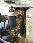
I was probing the left side of the terminal with my test light all looked good until I came down the terminal and hit the Orange (Heat) contact. It showed power but kind of arched when I touched it and blew the circuit breaker I just installed. The breaker is self resetting so it would kick every few seconds but blow again right away, I noticed that I could see smoke from what appears to be a grounding block (see picture). The wire that I circled I believe is the one that was giving the short. I am not sure where to go from here, I disconnected the battery main for now but I am not sure what the wire controls or why it could be shorting out. Any ideas?

Full Size Image

Thanks
Rc
 

Attachments

  • force.JPG
    force.JPG
    62.7 KB · Views: 6

bjhc100

Seaman Apprentice
Joined
Nov 17, 2006
Messages
40
Re: Force 125 Electrical Troubleshooting

I have the same engine as you and the little square black thingy with 4 wire leads is the rectifier. You should have dc terminals diagonal with a red wire +, and a black wire -. On the other diagonal the two ac terminals with green/yellow wires on each. It changes ac current to dc, and it is sensitive to shorting. You can check it with an ohm meter as follows.

1. Disconnect all wires from the rectifier. 2. Connect the ohm meter between the negetive terminal and one of the AC terminals. Note the meter, and reverse the leads. The meter should show continuity in one direction but not in the other. 3. Move one ohmeter lead to the remaining ac terminal. note the meter, then reverse the leads. The meter should show continuity in one direction , but not in the other. 4. Repeat this procedure with an ohmmeter connected between the positve terminal and alternately to each ac terminal. Meter should show continuity with the ohmmeter connected, one way but not the other. If continuity is indicated in both directions, or if no continuity is indicated in both directions, the replace rectifier.

This instruction is copied word for word out of the Clymer manual.. When I got my motor it had a blown rectifier, I went to my local marina and found a dealer who had Mercury forcce parts. I think it was about $35. I think you can order from Iboats or Sierra for less$$$. Good luck and stick with it.
 

rcracerx

Seaman
Joined
Nov 29, 2008
Messages
58
Re: Force 125 Electrical Troubleshooting

I have the same engine as you and the little square black thingy with 4 wire leads is the rectifier. You should have dc terminals diagonal with a red wire +, and a black wire -. On the other diagonal the two ac terminals with green/yellow wires on each. It changes ac current to dc, and it is sensitive to shorting. You can check it with an ohm meter as follows.

1. Disconnect all wires from the rectifier. 2. Connect the ohm meter between the negetive terminal and one of the AC terminals. Note the meter, and reverse the leads. The meter should show continuity in one direction but not in the other. 3. Move one ohmeter lead to the remaining ac terminal. note the meter, then reverse the leads. The meter should show continuity in one direction , but not in the other. 4. Repeat this procedure with an ohmmeter connected between the positve terminal and alternately to each ac terminal. Meter should show continuity with the ohmmeter connected, one way but not the other. If continuity is indicated in both directions, or if no continuity is indicated in both directions, the replace rectifier.

This instruction is copied word for word out of the Clymer manual.. When I got my motor it had a blown rectifier, I went to my local marina and found a dealer who had Mercury forcce parts. I think it was about $35. I think you can order from Iboats or Sierra for less$$$. Good luck and stick with it.

Hey thanks for the reply. I will test the rectifier using your instructions and let you know the results.

Can you think of why the rectifier would be smoking? As I said everything was fine for 5-10 minutes after I put the new circuit breaker in, it wasn't until I applied my test light to the Orange Heat circuit that it tripped. I had my light hooked up to the big starter ground bolt connected to the block. As soon as I probed that orange wire on the left side of the terminal she blew the circuit. I just don't understand that.

Thanks
Rc
 

moparman

Petty Officer 1st Class
Joined
Oct 14, 2008
Messages
314
Re: Force 125 Electrical Troubleshooting

DID you use a regular test light or logic probe? a regular test light sometimes allows feed back on electrical components,whereas a logic probe [using L.E.D.s] ,is a safe bet with no ground feed back to what your testing.keep us posted. MOPARMAN ROLL TIDE 12-1
 

rcracerx

Seaman
Joined
Nov 29, 2008
Messages
58
Re: Force 125 Electrical Troubleshooting

DID you use a regular test light or logic probe? a regular test light sometimes allows feed back on electrical components,whereas a logic probe [using L.E.D.s] ,is a safe bet with no ground feed back to what your testing.keep us posted. MOPARMAN ROLL TIDE 12-1

The test light was a $7 Walmart special so I doubt it was a logic probe light.

Also I noticed that I had wired my 12v panel switch incorrectly. I had the ground & positive on the wrong sides of the post. Is it possible that something tied into the Acc circuit could have helped short the wire going to the recifier?

Thanks
Rc
 

Frank Acampora

Supreme Mariner
Joined
Jan 19, 2007
Messages
12,004
Re: Force 125 Electrical Troubleshooting

First thing you need to understand is that the orange is the overheat OR temperature wire.

Depending upon how it was wired, it will either always have 12 volts when the ignition switch is on, or will always have 12 volts potential period.

The overheat switch is a normally open switch on the head. When it heats up, the bimetal bends and closes the switch 12 volts can now flow from the ignition switch through the buzzer or light and to ground on the head.

The only difference with the gauge is that the degree of heat varies the resistance of the switch on the head.and the gauge shows this as a temperature reading.

Proper wiring of the overheat circuit is: One wire of gauge or buzzer to "I" terminal. ("I" terminal only has power when ignition switch is on) Other wire to ORANGE wire in cable. Orange wire in cable to orange terminal on board, and orange in loom to head switch. Thus: when the ignition switch is OFF, no power will flow through the circuit even if the engine is overheated. This prevents the buzzer from sounding continuously when the engine is overheated but off--At that point, we have turned off the engine and don't need the annoyance of a constant buzzer.

SO, if you probe the orange wire to ground with the ignition on, you are creating a short.
 

rcracerx

Seaman
Joined
Nov 29, 2008
Messages
58
Re: Force 125 Electrical Troubleshooting

First thing you need to understand is that the orange is the overheat OR temperature wire.

Depending upon how it was wired, it will either always have 12 volts when the ignition switch is on, or will always have 12 volts potential period.

The overheat switch is a normally open switch on the head. When it heats up, the bimetal bends and closes the switch 12 volts can now flow from the ignition switch through the buzzer or light and to ground on the head.

The only difference with the gauge is that the degree of heat varies the resistance of the switch on the head.and the gauge shows this as a temperature reading.

Proper wiring of the overheat circuit is: One wire of gauge or buzzer to "I" terminal. ("I" terminal only has power when ignition switch is on) Other wire to ORANGE wire in cable. Orange wire in cable to orange terminal on board, and orange in loom to head switch. Thus: when the ignition switch is OFF, no power will flow through the circuit even if the engine is overheated. This prevents the buzzer from sounding continuously when the engine is overheated but off--At that point, we have turned off the engine and don't need the annoyance of a constant buzzer.

SO, if you probe the orange wire to ground with the ignition on, you are creating a short.

Thanks for the reply & the education.

So then I must have probed it with the key on and that is what caused the sparks and the curcuit breaker to blow. But when I removed the test light and the circuit breaker reset, something was still creating the short for it to keep blowing. What could I have damaged when probing it that would cause it to continue to blow the circuit? The ignition switch maybe? Or perhaps the actual head switch or maybe the buzzer? The smoke coming from the Red wire on the Rectifier is what worries me. I dont want to connect the battery again before I can determine the cause of the short & repair it. Any idea where to look first?

Thanks
Rc
 

Frank Acampora

Supreme Mariner
Joined
Jan 19, 2007
Messages
12,004
Re: Force 125 Electrical Troubleshooting

The red wire on the rectifier is 12 volts positive to the battery--directly to the battery. It goes down to the the red terminal then another red wire goes from that terminal to the circuit breaker. A third red wire goes from the breaker to the battery side of the starter solenoid (Battery positive). THUS: The circuit breaker cycling indicated a shorted rectifier--it can't be anything else. Full battery voltage and amperage is traveling up to the rectifier and going to ground.

Disconnect the red and black from the rectifier. Put an ohmmeter on the two terminals and I think you will find 0 oms each way. put the red lead on the red terminal and put the black lead on an engine ground. Again you will find 0 ohms. The rectifier is bad. Hopefully it shorted to ground.

Remove the two alternator leads and probe them with an ohmeter. It should show low ohms or continuity. Hope you don't show infinite ohms indicating that the short was through the alternator requiring replacement of the stator.

Break down and buy a VOM--volt-ohm meter. You can get a decent one for your purposes from Sears, Lowes, Pep Boys, etc. for about 20 bucks. Test lights are ok for some things but a decent VOM is much better and not that much more expensive.
 

rcracerx

Seaman
Joined
Nov 29, 2008
Messages
58
Re: Force 125 Electrical Troubleshooting

The red wire on the rectifier is 12 volts positive to the battery--directly to the battery. It goes down to the the red terminal then another red wire goes from that terminal to the circuit breaker. A third red wire goes from the breaker to the battery side of the starter solenoid (Battery positive). THUS: The circuit breaker cycling indicated a shorted rectifier--it can't be anything else. Full battery voltage and amperage is traveling up to the rectifier and going to ground.

Disconnect the red and black from the rectifier. Put an ohmmeter on the two terminals and I think you will find 0 oms each way. put the red lead on the red terminal and put the black lead on an engine ground. Again you will find 0 ohms. The rectifier is bad. Hopefully it shorted to ground.

Remove the two alternator leads and probe them with an ohmeter. It should show low ohms or continuity. Hope you don't show infinite ohms indicating that the short was through the alternator requiring replacement of the stator.

Break down and buy a VOM--volt-ohm meter. You can get a decent one for your purposes from Sears, Lowes, Pep Boys, etc. for about 20 bucks. Test lights are ok for some things but a decent VOM is much better and not that much more expensive.

Thanks for your help Frank.

I did as you said and below are my results:

Stator Test - I tested the 2 leads that were green with a yellow stripe after I removed them from the rectifier. My meter showed anywhere from .7-1.1 reading on the display. (There is also a purple wire connected under one of the Stator wires, what is that purple wire for?)

Rectifier Test - I connected between the red & black terminals on the rectifier and my meter showed .7. Then I connected between red & the ground on the engine block and my meter showed OL. What is OL ? Out of limits? Does that mean that only one side of the rectifier shorted since I got a .7 reading between the red & black?

So it looks like to me that I may have gotten lucky and only hurt the rectifier, a cheap lesson at $25.00 + $8 shipping, and I should have it by the end of the week. I ordered 152-9209 Chrysler rectifier hopefully it is the right part.

Now is the Stator an item that either works or not works, I mean could I have possibly caused damage that I will not know about until later even though the test reads okay?

Last question I promise (for today anyways :) ) Do you think that I caused this by my lack of knowledge probing the terminal block or should I look for something else before I apply battery power after installing the new rectiier. I dont want to risk blowing out another one if the original cause is still not known.

And about the Skeg. I will take a picture of mine but they didnt weld it thats for sure. It looks like they took some metal brace on a 45deg angle both side with bolts holding the Skeg on. It is definitley a backyard job but the guy said it had been like that for years. Is it worth it to have it welded on the correct way or is more of a cosmetic situation and should still serve its purpose.

Thanks for your time.

Rc
 

rcracerx

Seaman
Joined
Nov 29, 2008
Messages
58
Re: Force 125 Electrical Troubleshooting

Okay I am back with an update. There is good news and bad news. :(

I replaced the rectifier, cleaned all my grounds. Shot a little oil in the cylinders replaced the spark plugs & used a portable tank for fuel. Hit the key and she turned over...woot! But it wouldn't start. :( I checked for fuel and I could smell it was getting gas, perhaps too much gas as I saw some drips from the bowls on the carb. I hooked a spark tester up and checked all 4 cylinders and not a single one had a spark. :( My manual still has not arrived yet so I searched a little bit on the forum but did not find any useful information of what to check next. I did see one post about disconnecting the white wire (Kill switch?) on the engine terminal block and I did but I still did not get any spark on any cylinder.

Can anyone give me some steps to take next to troubleshoot why I have no spark? I don't have alot of money to try swapping out parts. Hopefully I have the tools and technical ability to get this fixed because I dont think I could afford to have a marine technician repair it. That is if I could even find somebody in the South Jersey / Philly area to work on the Force motor, every place I called locally for parts seemed to sigh when I mentioned Force motor. :)

So I guess my good deal on a boat isnt looking so good right now. :) :) I really hope I don't have to say you were right to my wife who said it was a bad idea from the start...lol

Thanks
Rc
 

moparman

Petty Officer 1st Class
Joined
Oct 14, 2008
Messages
314
Re: Force 125 Electrical Troubleshooting

try master tech marine ,they have a break down that you can follow ,and check things out. IT helped me when I worked on my 1988 125 force,before my manual came in . Keep us posted on your progress. MOPARMAN ROLL TIDE 12-1
 

pnwboat

Rear Admiral
Joined
Oct 8, 2007
Messages
4,251
Re: Force 125 Electrical Troubleshooting

Take a look at this site. It might be helpful.

http://cdielectronics.com/Downloads/tabid/55/language/en-US/Default.aspx

There is a section where you can download a troubleshooting guide for various outboards. Look in the Mercury/Force CDM ignition section once you download the "Troubleshooting Guide".

Also there is a download that has the Force DVA charts which show various voltage and resistance readings for the stator, coils etc.

Hope this helps. Good luck!
 
Top