1994 Force 70hp wiring diagram

leander borg

Cadet
Joined
May 26, 2008
Messages
18
I bought Seloc Force outboards repair manual. I noticed the wiring diagram does not match exactly to my outboard wiring.
Can please someone send me the exact wiring diagram for this motor? Maybe the Clymer Manual has the exact diagrams. Please help, I realy want to fire up this motor.

Thanks
 

Attachments

  • force70_1994 .jpg
    force70_1994 .jpg
    83.5 KB · Views: 14

roscoe

Supreme Mariner
Joined
Oct 30, 2002
Messages
21,665
Re: 1994 Force 70hp wiring diagram

Sorry, can't provide a wiring diagram for you, but...

Your regulator has been replaced with an aftermarket model which may use different color wiring.

Also, your motor does not appear to be a 1994 model.
The fuel pump is an older 2 stage pump, which wasn't used after the 1992c model.

Did you just pick this motor up? Looks like the thermostat housing is in need of care, and clamps on fuel lines are always a good idea.
 

leander borg

Cadet
Joined
May 26, 2008
Messages
18
Re: 1994 Force 70hp wiring diagram

When I took that photo I was removing the thermostat and water pump to replace with a new one .The casing had only some corrosion scaling, notting to worry about. It started and ran like a champ when I bought it. Factory compression reading! the cowling is this one here, maybe you will know better than me what year it is.
Last week I removed the rusted plate where the 3 coils are fixed, to have it painted. In order to do so I diassambled some of the wiring harness and after painting it, I connected everything as before.

Yesterday I cranked the motor several times. The strange thing is that there is spark on all of the 3 plugs but the thing does not want to kick!
Is the prime pump supposed to click when I push the the ignition botton in ?
 

Attachments

  • 1.JPG
    1.JPG
    43.5 KB · Views: 7
  • 2.JPG
    2.JPG
    42.2 KB · Views: 7

roscoe

Supreme Mariner
Joined
Oct 30, 2002
Messages
21,665
Re: 1994 Force 70hp wiring diagram

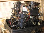
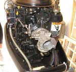
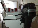
Definitely not a '94 according to the cowling graphics, or the fuel pump.

If there is an id sticker on the motor, it should be on the transom mounting bracket next to the tilt n trim motor.


Yes the fuel enrichment valve will make a very faint click when you push in the key.
Probably won't be able to hear it open unless you have your ear next to it.

This motor does not have a traditional choke, but the fuel enrichment system, that releases fuel directly into the intake manifold. It only releases fuel into the manifold using the pressure from the fuel line, so you need to squeeze the fuel line bulb first.

To start this motor:
open fuel tank vent if you have portable fuel tanks
connect the fuel line
squeeze fuel line primer bulb until it gets firm

Advance the throttle to 3/4 to full position
you have to release the shift mechanism on the controls to do this.
On the earlier Commander 2000 controls, you pull the entire shift handle to port, then push forward.
On the Commander 3000 controls, you push the button at the center of the shift handle, then push forward.

Push in the key and turn it to the start position.
If it does not fire in 5-7 seconds, release the key.
Now try just turning the key without pushing it in.
When it fires, release the key and start pulling the throttle back to keep the rpm's from going over 1500.

If the motor starts to die, you can tap the key in for a second, to give it a little more fuel.

I miss my 70 hp, it was a great motor for me.
 

bertthedefender

Seaman Apprentice
Joined
Aug 12, 2007
Messages
36
Re: 1994 Force 70hp wiring diagram

I'll send you a diagram I used last year when repairing the ignition on my 1991 70hp - this was correct for the standard ignition components, but as roscoe says, you have an aftermarket rectifier/regulator and it also looks like you also have the later (redesigned) red stator peeping out under the flywheel.

Your wiring may be different to that in the seloc manual, as the rectifier is a one-size-fits-all model, the same as I used to replace the faulty one on my motor. This has more wires than are needed for the 70hp and one of the red wires should just be taped up:

http://cdielectronics.com/Portals/0/installsheet/194-5279.pdf

There may also be some difference in the stator wiring too, as the CDI/Rapair part which I used has multiple applications for 2/3/4 cylinder motors and has to have the blue/white and red/white wires connected to ground. I mention this as this part is a direct replacement for the red stator too, so you may find yours rigged up in a similar way.

Hope that helps,

B.
 

leander borg

Cadet
Joined
May 26, 2008
Messages
18
Re: 1994 Force 70hp wiring diagram

Thanks for your help and diagram.
The wiring was ok, cloked fuel in carb was the problem. Sprayed some WD40 in the carb fuel inlet, and after it is started up!
http://www.youtube.com/watch?v=9aP1UNhqdds

The tachometer is set on 6P, should it be set like this on this engine?
I`m getting 1000rpm @ idle

I still have some problems with the temperature guage, I ran a wire from the sensor to the guage and connected it to the send connector. After warmup of the engine , the guage needle moves very little and does nevver gets over 120 ferenhite ! any ideas ?
 

bertthedefender

Seaman Apprentice
Joined
Aug 12, 2007
Messages
36
Re: 1994 Force 70hp wiring diagram

You probably need to set the tacho to 1/2 the number of alternator poles. Yours is currently set to 6 Pole which I think is correct. Setting it to anything lower would make the RPMS appear faster I think.

Re the temperature guage - my motor doesn't have one so I don't know what temperature it runs at! But do you have the correct sender for the guage?

On your video I can see a capillary coming from the top of the motor - do you have a water pressure guage too? Thats something i'd like to fit to mine.
 

leander borg

Cadet
Joined
May 26, 2008
Messages
18
Re: 1994 Force 70hp wiring diagram

Yep I have the water pressure guage.
The number of little black cores on the alternator disc adds up to 12 . ie.12 pole. therefore I adjusted the setting to 6P because it was set on 5P on the vid. Now it shows 900rpm@idle.
Yesterday I tried to figure out the guage problem. The guage is fine because if I short the SEND connector (on guage) to ground, the needle goes all up to the right. Therefore the sender may be the problem. When cold the sender gives a reading of 850ohms on the ohmmeter.
I have the standard mercury guage. Can I only buy a new sender to fit this type of guage, or does they come as a sender+guage kit ?
 
Top