Battery Voltage

Lawns570

Seaman Apprentice
Joined
Jul 18, 2015
Messages
49
96' 75hp Force. When I put my meter on the battery it reads about 12.8V... I will also put out the disclaimer its a cheap Multimeter, but I think it gets me close. When I start the boat up and I stick the meter on it, the Voltage jumps. It will stay about about 13.5-14v for a second then drop to 9 then 1 then right back to 13... My reading on my dash doesn't jump around.. it seems to stay around 13.5v....
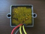
I recently changed my Voltage Regulator/Rectifier.... when I shut the engine off it ready 12.8v with no jumping around... Is this something wit my meter? Bad regulator? I can't imagine my battery voltage drops to 1v then immediately back to 13.
 

fhhuber

Lieutenant
Joined
Jun 19, 2014
Messages
1,365
The battery isn't jumping voltage like that... They just can't.

Analog dial type meter and vibration bouncing the needle could do it.

it kind of sounds like a poor connection between battery and meter.
 

Lawns570

Seaman Apprentice
Joined
Jul 18, 2015
Messages
49
I went an grab another Multimeter. The symptoms continue.I put the old volt. regulator back on and the problem is the same. I took the old one off because it was showing it was charging at 17v. The new one is holding around 14v or so while running.. Both have the voltage bouncing all over the place... Also....... The tachometer isn't working properly... It's ready maxed out,, past the 8,000 rpm mark
 

tommarvin

Ensign
Joined
Nov 22, 2015
Messages
999
1. When tachs are or get maxed out ,they are usually broken and you need a new tach.
2. If your batterys aren't getting overcharged you don't have a problem. You want a Regulator/rectifier, not just a regulator.
3. Are there any problems with your motor?
 

jerryjerry05

Supreme Mariner
Joined
May 7, 2008
Messages
17,926
Tom.It's the same thing.Rectifier/regulator same,same.

If the signals jumping then it sounds like there is a bad connection somewhere??
As long as it's charging and doesn't overcharge I wouldn't worry.
The tach clean the connections and if it still jumps, WD-40 and on the tach is a black screw that's used for changing between the 3/4/5 cyl. motors.
Try switching the black screw if you have one.
 

Jiggz

Captain
Joined
Oct 23, 2009
Messages
3,817
The best way to troubleshoot this is to disconnect the tach signal for now (this is easier done at the connectors inside the engine cowl). With the motor running, read the AC voltage coming off the stator through the input terminals or connectors (or using needle point test probes to pinch thru the wire insulation) of the rect/reg. Typically, with the engine idling around 1000 RPM, the AC voltage should be around 16~20 Vac. It will be fluctuating a little bit but not a whole lot. Of course, this all depends on the smooth idling of the motor. If there is a large fluctuation, i.e. 1Vac ~ 20 Vac, there could be a problem with the, rect/reg, stator or the magnets under the flywheel. Remember, there are two separate circuits (ckts) in the stator, one for the power ckt for the CDM and another for the charging ckt for the battery. Obviously, with large fluctuation on the input the output will normally be fluctuating also.

If the rect/reg input voltages are not fluctuating, then read the voltage output with a DC meter. Again the output should be around 13~16 Vdc with very little fluctuations. If there is a large fluctuation, there is a good possibility the new rect/reg could be faulty (if input signal do not fluctuate as much). If there is no fluctuations, then stop the motor and reconnect the tach signal input. Test again from the input and output terminals of the rect/reg. If the problem shows back up then you can conclude the tach is affecting the input of the rect/reg hence, also the output.
 

Lawns570

Seaman Apprentice
Joined
Jul 18, 2015
Messages
49
Ok I will try your suggestions tonight. I put the old volt. regulator/rectifier back on last night... the voltage is still jumping around.. this time however the tachometer goes to 1,000 rpm and doesn't move, even when I hit the throttle.

I'll report back tonight after I run the tests.
 

Jiggz

Captain
Joined
Oct 23, 2009
Messages
3,817
Is the replacement or new reg/rect an OEM version or non-OEM? I ask this because on some non-OEM units, for some reasons there is a specific connections required for the input wires from the stator, i.e. the two yellow or grn/yel wires. When connected improperly, the rectifier still works but gives a bad tach signal. And the fix is to reverse the connection of the two input wires.
 

Lawns570

Seaman Apprentice
Joined
Jul 18, 2015
Messages
49
I took the yellow wires and swapped them as Jiggz suggested. It's not an OEM voltage reg. I also disconnected the tach wire. The voltage still seemed to bounce around when testing at battery. As soon as I plugged in gray tach wire the needle would wind around and max out
 

Jiggz

Captain
Joined
Oct 23, 2009
Messages
3,817
Can you post a pic of the voltage reg/rect both the new and old one. Make sure you label which one is which.
 

Lawns570

Seaman Apprentice
Joined
Jul 18, 2015
Messages
49
No Title

Here is the old one.. the new 1 looks the same except its not clear it black.
 

Attachments

  • photo242567.jpg
    photo242567.jpg
    6.5 KB · Views: 0

Lawns570

Seaman Apprentice
Joined
Jul 18, 2015
Messages
49
Jiggz.. can you give more detail on testing the yellow stator wires for AC DC voltage... when testing AC voltage do I put 1 lead on each of the yellow wires.. when testing DC I put 1 lead on a yellow wire and the other on a ground source?? Should I do this while the Yellow stator wires are still plugged into each other?
 

Jiggz

Captain
Joined
Oct 23, 2009
Messages
3,817
To test the input voltage which is AC, make sure the tester or multimeter is set for Vac (V~), place each test probe on each of the yellow wires.

To test the output voltage which is DC, make sure the tester or multimeter is set for Vdc (V=--), place the red probe on the red wire (of the reg/rect) and the black to ground.

All wires should be plugged in to the reg/rect. You might have to use needle point piercing probes to pierce through the insulation to get a reading. If you do not have piercing probes, use two small safety pins (or thumb tacks) to pierce through each wire. Make sure you do not short or make any of the pierced wires get in contact with each other if you use safety pins. You want to do two sets of readings, one with the gray wire (tach signal wire) connected and the other when it is disconnected. Make sure you write down you observations.
 

Lawns570

Seaman Apprentice
Joined
Jul 18, 2015
Messages
49
AC Voltage Bounced between 24-6 Volts
DC was between 14-6 Didn't seem to matter whether TACH was plugged in or not.
 

Jiggz

Captain
Joined
Oct 23, 2009
Messages
3,817
What about the motor, was it surging as well? Remember the voltage generated by the stator is directly proportional to the speed of the flywheel which is the speed of the motor. If the motor is surging then you want to fix that first before focusing on the regulator. Better yet, try manually increasing the motor rpm to about 1200~1500 RPM to see if the motor stabilizes and then take voltage readings again.
 

Lawns570

Seaman Apprentice
Joined
Jul 18, 2015
Messages
49
I didn't hear the motor surging however the Tach isn't working properly. Normally its maxed out 8,000 plus RPM's. Yesterday it was ready like 3,000rpms, but it was just idling so I doubt it was actually running at 3,000 rpms.
 

Jiggz

Captain
Joined
Oct 23, 2009
Messages
3,817
Try the test again. This time pay attention to the input voltages while listening to the motor rpm. Small voltage fluctuations on the output (albeeit also on the input side) side of the regulator is normal but it should never at any time go below the battery voltage. Make sure the red wire off the reg/rect is connected to the ckt bkr that is also connected to the battery. Make sure the ckt bkr is not tripped. You can do this by pushing in the small black tab on the ckt bkr.
 

Jiggz

Captain
Joined
Oct 23, 2009
Messages
3,817
My bad, in your case there is not ckt bkr. In fact, looking at my diagram the reg/rect connects directly to the battery through the starter solenoid. Hence, if the motor is not running you should be able to read the battery voltage from the output terminal of the reg/rect and to ground. Red probe to the red wire and the black wire to ground. If not, then there is something wrong in the wiring or wires are not connected properly. Trace the red wire off the reg/rect and see if it connects directly to the large (+) terminal of the starter solenoid. This is the same terminal where the large red positive battery terminal is also connected.

If wiring is correct, the bottom line is you should never read voltages from the reg/rect lower than your battery voltage.
 
Last edited:
Top