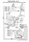
Force 125 wiring diagram for the solenoid

shargis2012

Recruit
Joined
Dec 15, 2011
Messages
5
I replaced the solenoid, it has two large posts on the top and two smaller posts, when I have the wires connected and turn the key it clicks one time.Would that be an indication that the wires are hooked up wrong or another problem, when I check the post connected to the starter I have no power and when I check the smaller post with a yellow wire I have no power. Any suggestions. Thanks in advance
 

pnwboat

Rear Admiral
Joined
Oct 8, 2007
Messages
4,251
The small yellow wire, and the large cable going to the starter only have voltage when the key is in the start position. Once you release the key, voltage is no longer applied to those wires. The other small post opposite the yellow wire should have a small black wire on it that goes directly to ground. The small black wire should not be connected to the same post as the small yellow wire. Is that connected correctly?
 

shargis2012

Recruit
Joined
Dec 15, 2011
Messages
5
Those two wires are on separate posts, does it matter which one is connected to the one marked with a s or the one with the I. I connected the yellow wire to the I thinking that was for the ignition switch.
 

Frank Acampora

Supreme Mariner
Joined
Jan 19, 2007
Messages
12,004
Since the solenoid is basically an electromagnet coil, it usually does not matter which SMALL post the yellow wire attaches to. SO: The battery cable attaches to the large post closest to the front of the engine while the starter cable attaches to the other large post. Typically the yellow wire attaches to the small post closes to the center of the engine while the ground connect to the other and downward to one of the mounting bolts.

Now, there is a small red wire that also connects to the battery cable post. This supplies power to the ignition switch AND recharges the battery while the engine is running. If it is not attached, there will,be no power to the ignition switch.

The other small post on top of the solenoid must be attached to a good ground. Early solenoids were grounded through the mounting bracket and do not require a separate ground. Later solenoids are NOT grounded through the case and MUST have a separate ground.

The yellow wire travels back to the neutral interlock switch and then to the ignition switch. A broken wire here or a non connected one will prevent the engine from starting. SO will the misalignment of the switch and cam. The white button MUST be depressed in neutral.
 
Last edited:

Jiggz

Captain
Joined
Oct 23, 2009
Messages
3,817
No Title

Here's a wiring diagram to help you navigate. It also show all the connections to the ignition switch.
 

Attachments

  • photo220492.jpg
    photo220492.jpg
    105.6 KB · Views: 35
Top