Wiring Smoked Once...

yknotgo

Seaman
Joined
Sep 8, 2012
Messages
51
Hello all,
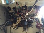
A few months ago, I took my boat out fishing. While idling on a spot, I noticed smoke from my cockpit area all the way down my gunwale area. I turned off the engine immediately, and the smoking stopped. I started the engine again, and the wiring started smoking again. Shut down and got towed. Since then I have contemplated back and forth to keep the boat, or cut my losses and let it go to someone how has the time it needs to get going again. I'm currently at the point I want to give it a shot. First thing I need to figure out is what caused the issue. The alternator was rebuilt recently, and a wire melted coming off the ignition switch, a hot wire. There is a ground wire that is shared with the ignition and the volt meter. No idea if that has anything to do with the problem. Next, I can now start the engine, turn on appliances, and everything seems fine. However, I noticed too that if I turn on appliances, the volt meter drops. Is this due to bad alternator, or wiring/connection issues? I am considering attempting to re-wire it myself. I bought the book "Boat Owner's Illustrated Electrical Handbook" by Charles Wing. I understand some stuff, but not as much as I feel I should to attempt this yet. But, I know there is plenty of help here, and info here and on the web. I noticed that I don't notice any fuses in my wiring, none associated with the switches, nor a fuse block that I've located. With that said, I'm confused on some things. One is, if I order something like this, https://www.bluesea.com/products/8261/Contura_Water_Resistant_12V_DC_Panel_-_8_Position, do I need a fuse block still since there are fuses for each switch? Also, I tried figuring out where the power to the console comes from by following the large wire coming off my battery switch, and noticed it went to the starter, then the wire from there went to the engine. I didn't get beyond that. Does this sound right? I attempted to attach some photos to give you an idea what I have, and some things that I noticed that I feel may be part of the problem I experienced. Sorry for the long read. If I have too much going on in this one thread, and need to make multiple threads, please advise me to do so.
Thank you very much for reading this, and helping me,

Grady

188 (1024x768).jpg 189 (1024x768).jpg 190 (768x1024).jpg 191 (768x1024).jpg 196 (768x1024).jpg 197 (1024x768).jpg 198 (1024x768).jpg 199 (1024x768).jpg 201 (1024x768).jpg 227 (800x600).jpg


233 (800x600).jpg


234 (800x600).jpg


No appliances on
235 (800x600).jpg


Flood light, VHF, and cabin light on.
236 (800x600).jpg

Above items back off.
237 (800x600).jpg
 

Attachments

  • 188 (1024x768).jpg
    188 (1024x768).jpg
    33.6 KB · Views: 0

alldodge

Moderator
Staff member
Joined
Mar 8, 2009
Messages
40,754
If your using the blue sea panel you would nott need to use an additional fuse panel unless you needed more circuits. That said the panel max current rating is 45 Amps with a 12V system

8261.jpg


From the looks of what happened in the overheat is caused by corrosion. Resistance is being built up from the corrosion happening and the resistance is creating more heat. If you cleaned everything and replaced some of the terminals you should be good. The voltage drop with everything running can be caused by resistance, engine rpm (alternator output).
 

yknotgo

Seaman
Joined
Sep 8, 2012
Messages
51
Thanks for the info ALLDODGE. Would that also explain by chance why the alternator is not putting out 14 volts while running? I've even tested it's output at the batteries to if there is a difference. There is a little bit more showing at the batteries, but not 14. But, I didn't check when I took the pictures above. That was the best looking look coming from the volt meter gauge in the last few starts.
I looked at the installation diagram of the blue sea panel, and it showed that I will still need a neg. buss bar.
Can I hook up a couple of items to one switch? I know each switch has it's own amp. limits. I was thinking of like putting the gps, vhf, and fishfinder all on one switch as those three are always on for me at the same time. RADAR a separate switch, etc. I know ABYC standards say no more than 4 connections I think on one terminal, I don't plan to do more than 3 on any given one. Also, do you have other recommendations on switch panels? I wanted one with 12 kind of but didn't find one yet. I'm really trying to plan this out. And I would like to re-wire that cluster and clean it up. Unless it appears un-necessary and a waste of time and money. I don't have much of both, but I want to do it right.

Thanks again.
 

gm280

Supreme Mariner
Joined
Jun 26, 2011
Messages
14,593
I agree 100% with ALLDodge's assessment. You presently have circuit breaker switches. Those are your circuit protection devices. However, seems some of them may be corroded inside as well as outside also! I'd start with taking lots of quality pictures and at every different angle you can get. Then put label markers on each wire/connector before doing anything else. Example, a wire going to the bilge pump would be labeled "bilge", or some thing like that on the wire. After labeling everything, start removing those wires and either clean each one individually OR remove the entire circuit breaker block assembly and clean them and check them for shorts or opens. Myself, being an Electronics type person, I would remove everything and do the job properly and totally the correct way. But others have their own ways of doing things like this, and it honestly doesn't matter if the end results work! I would also cut back so many of those over length wire bundles in that areas too. That only creates extra resistance and looks bad as well. A good clean nice breakout wiring method is the proper way. I'm sure others will chime in with suggestions as well... But you have to clean both ends of every wore. Even the wire connectors on all the meters too. And certainly don't forget the battery connectors either. Electricity doesn't like corrosion even a little bit! JMHO!
 

yknotgo

Seaman
Joined
Sep 8, 2012
Messages
51
Thanks for the advice gm280. I want to clean it all up, get rid of excess wires, etc. Taking the time to label everything is a very good idea. I read it all the time and still haven't told myself to do so. Now that you mentioned it, for some reason, it's sticking. That might be my project this weekend if I have time. Label the wire that goes to each switch. So, you're saying the current switches are individual breakers? If so, then that explains the no fuses, right?
Thanks to everyone taking the time to read through this and to help when you can. I appreciate it very much.

Grady
 

alldodge

Moderator
Staff member
Joined
Mar 8, 2009
Messages
40,754
Thanks for the advice gm280. I want to clean it all up, get rid of excess wires, etc. Taking the time to label everything is a very good idea. I read it all the time and still haven't told myself to do so. Now that you mentioned it, for some reason, it's sticking. That might be my project this weekend if I have time. Label the wire that goes to each switch. So, you're saying the current switches are individual breakers? If so, then that explains the no fuses, right?
Thanks to everyone taking the time to read through this and to help when you can. I appreciate it very much.

Grady

Yes your switches are breakers. While fuses will protect the circuit faster then breakers they can be an issue they can also have another area where corrosion can take place. The breakers are sealed and the fuse will have two ends where corrosion can happen.

Would be nice if you had the ability to slowly increase current and test each one of your breakers. In most cases the breakers could be just fine on the inside, may only be outer surface corrosion. If you keep the breakers you could go to similar switches but without fuses.

Use soldered connections where you can to keep down on other corrosive issues. Where solder is not used make sure to seal the ends with silicone grease, liquid tape or heat shrink tubing. From your pics it looks like you may be in salt water, and if so sealing is even more important.

Main buss bars for Ground and 12V are real good to have. They can be feed under the helm with 6 to 10 AWG wires and then feed everything else from the through breakers and/or fuses.

As for the voltmeter readings, next time you run measure the voltage directly off the alternator. If the ALT reads in the 14.5 (+/- a little) you are good. If it's lower check to see if the ALT is getting hot. If your good at the ALT and not at the batteries then there is more corrosion.
 

gm280

Supreme Mariner
Joined
Jun 26, 2011
Messages
14,593
Again another great post from ALLDodge. The only thing I would add to his comments is read the output from the alternator while running the RPMs up. Idle RPMs will not do much with charging batteries and will read the lowest voltage levels at idle.
 

tblshur

Senior Chief Petty Officer
Joined
Aug 24, 2011
Messages
688
i think i would also turn all breakers off, then turn on one at a time and try to identify the wire that got hot and what it goes to, may be bilge pump, especially the one that makes the voltmeter drop. good luck:joyous:
 

yknotgo

Seaman
Joined
Sep 8, 2012
Messages
51
Thanks again for the input. As I continue thinking and reading related posts to wiring, I have another question, more related to re wiring. I don't really need a switch for items such as VHF, fish finder, gps, and radar since the devices themselves have power switches. What I could do is run them off of a fuse block with their appropriate fuses right? If I'm getting away from my original topic and should start a new thread, please let me know. Thanks again. I'm starting to get a little excited for this project. One thing I'm confused about is all the wires coming off the gauges. Why so many of them? Is that common?
 

alldodge

Moderator
Staff member
Joined
Mar 8, 2009
Messages
40,754
Thanks again for the input. As I continue thinking and reading related posts to wiring, I have another question, more related to re wiring. I don't really need a switch for items such as VHF, fish finder, gps, and radar since the devices themselves have power switches. What I could do is run them off of a fuse block with their appropriate fuses right? If I'm getting away from my original topic and should start a new thread, please let me know. Thanks again. I'm starting to get a little excited for this project. One thing I'm confused about is all the wires coming off the gauges. Why so many of them? Is that common?

Your discussing wiring of your helm, anything that pertains to that is on the same subject, no need to start another thread.

Correct, anything with a power switch does not need another switch. As you said so long as the power wire is feed by a fuse sized appropriately. All gauges will have 12V power, Ground and sender wire. They will also have a feed to the light bulb inside the switch which is connected to your Navigation light switch.

http://www.boatfix.com/merc/techbk/96/96hgd4.pdf
 

gm280

Supreme Mariner
Joined
Jun 26, 2011
Messages
14,593
You talk about so many accessories that have their own power switch, and that is true! You really don't need additional switches for those accessories. However, If you are like me (I surely hope not), then I like the option to control everything via a single switched location. What I'm saying is, after a long day on the water, one single accessory switch is much easier to simply turn off then moving around to each individual power switch on those accessories, but that IS just my opinion. You can wire your own boat anyway you like... Just make sure each accessory has its own fuse or breaker to protect it.
 

UncleWillie

Captain
Joined
Oct 18, 2011
Messages
3,995
Corrosion will cause the area of corrosion to heat up, but it will not cause the circuit to draw more power.
Your main power lead is melting because of excessive current, It is doubtful the alternator has anything to do with the melting issue.
I suspect that the wiring overheats when you turn ON the ignition switch, not starting the Engine.
Key ON, Engine OFF, would have the same result.

There is a short causing excess current somewhere in the circuits connected to the ignition switch.
The circuits on the breaker panel ALWAYS have power so turning OFF the engine would not stop the melting if the problem were in the Panel Circuits.
The main power lead from the battery to the Breaker Panel and Ignition switch should have a ~30 amp fuse in it, located near the battery to prevent just this type of problem.
 

yknotgo

Seaman
Joined
Sep 8, 2012
Messages
51
Thanks again for the advice. I'm considering starting to order some things for the rewire. I'm currently planning to get most of my things from Amazon as it seems to be cheaper than Port Supply. As of right now, below are the links to what I think I need.
2 of these, one for Pos. and one for Neg. http://www.amazon.com/gp/product/B0091VHLW4/ref=ox_sc_act_title_3?ie=UTF8&psc=1&smid=ATVPDKIKX0DER
http://www.amazon.com/gp/product/B001P6FTHC/ref=ox_sc_act_title_4?ie=UTF8&psc=1&smid=ATVPDKIKX0DER
http://www.amazon.com/gp/product/B000K2O0T0/ref=ox_sc_act_title_5?ie=UTF8&psc=1&smid=ATVPDKIKX0DER
http://www.amazon.com/gp/product/B000NUXDR4/ref=ox_sc_act_title_1?ie=UTF8&psc=1&smid=A3K90JHFOGRITA
http://www.amazon.com/gp/product/B000NV0HE0/ref=ox_sc_act_title_2?ie=UTF8&psc=1&smid=A1YUR915BM42I1
The 6 gauge wire is for running from the power source to the busses. From the busses, power will go to either the fuse block to device, or to the switch board. Am I planning this out correctly? Is the 6 gauge wire sufficient? I haven't measured how much I will need exactly, but I'm being conservative and thinking I'll need 20', but it may be closer to 15'. My boat is 22'. And for the power source, I have two batteries that are connected to a Perko battery switch. From there it appears the power goes to the starter. I'm unsure how I get power to the console area currently. What is the normal route? Also, what else may I be missing from my shopping list? I know the connectors, a good crimping tool, and wire to connect the devices. Not sure how to go about buying the connectors as I'm assuming I'll just need one or two sizes. Not sure though, so thinking I should wait.
Also, here is a list of the known appliances I can think of on my boat: Volvo/Ford 351W Fuel injected engine, trim motor for trimming outdrive (wired to throttle lever), trim tabs, bait pump, two bilge pumps, blower (may need to install new one), fish finder, radar, GPS, VHF, Nav lights, cabin light, Halogen Flood light (want to convert to two LED spread lights), want to install a stereo (basic one with 2 speakers, no Subs or anything), anchor winch, need to install anchor light, auto pilot, and windshield wiper motor. I very well may have a thing or two I forgot about. I just thought I'd give the list out to maybe help you know better what I'm working with and trying to power. I use the boat for fishing in the ocean and do spend the weekend on it sometimes fishing at the local islands.

Thank you so much for your time everybody. I hope to spend the weekend labeling the current wires, taking more photos, and making measurements and plans on how/where to install the new fuse block, switchboard, etc.

Grady
 

yknotgo

Seaman
Joined
Sep 8, 2012
Messages
51
You talk about so many accessories that have their own power switch, and that is true! You really don't need additional switches for those accessories. However, If you are like me (I surely hope not), then I like the option to control everything via a single switched location. What I'm saying is, after a long day on the water, one single accessory switch is much easier to simply turn off then moving around to each individual power switch on those accessories, but that IS just my opinion. You can wire your own boat anyway you like... Just make sure each accessory has its own fuse or breaker to protect it.

Thanks for the input. I may very well run a switch for everything. I'm actually starting to think I may want to get two smaller fuse blocks and have a switch to each, for smaller circuits. Either way, I unplug my electronics (Radar, GPS, and Fish finder) after each outing and lock them in the cabin so not get stolen. But, I can see myself accidently leaving something on and batteries drain. I actually did it once, forgot to turn of my electronics switch and the vhf was on. 2 weeks later, no juice.
 

UncleWillie

Captain
Joined
Oct 18, 2011
Messages
3,995
6 Awg is good for 50 amps. and it will need a 50 amp fuse at the battery end.
The Volvo/Ford 351W Fuel injected engine, trim motor for trimming outdrive (wired to throttle lever), and trim tabs, are not powered through the fuse block.

The two bilge pumps can be wired to a switch but will still need their own float switches and fused power leads attached directly to battery.
The switch might be able to turn them ON but should not be able to bypass the float switches.
The day you forget to set the switch correctly, will be the day before you swamp the boat.
 

yknotgo

Seaman
Joined
Sep 8, 2012
Messages
51
6 Awg is good for 50 amps. and it will need a 50 amp fuse at the battery end.
The Volvo/Ford 351W Fuel injected engine, trim motor for trimming outdrive (wired to throttle lever), and trim tabs, are not powered through the fuse block.

The two bilge pumps can be wired to a switch but will still need their own float switches and fused power leads attached directly to battery.
The switch might be able to turn them ON but should not be able to bypass the float switches.
The day you forget to set the switch correctly, will be the day before you swamp the boat.

Thanks for the input. So are you saying that I should supply the power from my battery switch? If so, I would fuse it after the battery switch correct? As for the bilge pump, I have a float for the aft one (my main pump) that is wired directly to the battery. However, it does not have a fuse, unless it is in the float switch itself, something I should look into, and if not, install an in-line fuse.
And lastly, does anybody have an idea what a winch normally draws? I have a Powerwinch brand on my boat, and that's about all I know. I think the label that tells me the model number on it is gone. I think that is the appliance that will draw the largest amount of electricity. Does that sound right? I know my dad had a boat where the winch had a thermal circuit breaker I believe. Is this standard practice for protecting you wiring from winches?
Thanks again for all the help. I need to start trying to draw all this out too. That is not at all my specialty.
 

alldodge

Moderator
Staff member
Joined
Mar 8, 2009
Messages
40,754
Need to run the winch direct from the battery with it's own cables, and correct use thermal breakers. The thermal breakers will reset after cooling down if they trip open.

Most of what your running will need no more then a 10 AWG but running a 6 AWG wires is good but IMO maybe an over kill but will not hurt a thing
 

yknotgo

Seaman
Joined
Sep 8, 2012
Messages
51
Need to run the winch direct from the battery with it's own cables, and correct use thermal breakers. The thermal breakers will reset after cooling down if they trip open.

Most of what your running will need no more then a 10 AWG but running a 6 AWG wires is good but IMO maybe an over kill but will not hurt a thing

I agree that I may be over kill. I was going to go with 8 for my power leads, but on Amazon, the 6 is cheaper for some reason, so I figure that since it won't hurt anything, I'd go with that. As for the winch, any idea what size wire I should use for that. It will be making approx. a 25-28' run most likely one way, so 50-56' round trip. The wire that I see run on the inside of my cabin doesn't look that large, maybe 10-12 gauge, but I don't know my wire sizes that well either. What size thermal breaker? And it should be closer to the battery end correct?
Thanks again everyone.
 

alldodge

Moderator
Staff member
Joined
Mar 8, 2009
Messages
40,754
I agree that I may be over kill. I was going to go with 8 for my power leads, but on Amazon, the 6 is cheaper for some reason, so I figure that since it won't hurt anything, I'd go with that. As for the winch, any idea what size wire I should use for that. It will be making approx. a 25-28' run most likely one way, so 50-56' round trip. The wire that I see run on the inside of my cabin doesn't look that large, maybe 10-12 gauge, but I don't know my wire sizes that well either. What size thermal breaker? And it should be closer to the battery end correct?
Thanks again everyone.

The wire size and breaker will depend on the size winch. Found one which indicates a 25AMP breaker and if it's the same size then 10AWG wire is good
http://www.powerwinch.com/powerwinch/controller?action=product&c=3&p=17
 
Top