Gauge issues

Gradywhite3535

Chief Petty Officer
Joined
Dec 29, 2012
Messages
480
I have my gauges all hooked up the way the diagram shows. When I put the test light on the fuel gauges sender terminal it lights up but only about 5%.then when I use my voltmeter it shows 9.75 but on the ignition terminal it's showing 12.35. Does that mean my gauge is broken? The light on the fuel gauge does light up. Thanks
 

sam am I

Commander
Joined
Jun 26, 2013
Messages
2,169
Re: Gauge issues

No and whats the "Issues"? You never said, was the needle all the way to left? Right? Is there gas in the tank?

Switched 12V to "I"? Fuel sender wire coming from tank to "S"? And a ground to "-"? If you haven't already, put the test stuff up, put some gas in that tank.......Hit the key and let the ole Megatron do its magic!!

fuel gauge.jpgfuel gauge 1.JPG
 
Last edited:

Gradywhite3535

Chief Petty Officer
Joined
Dec 29, 2012
Messages
480
Re: Gauge issues

I'm trying to get my gauges to work. I have it wired like the diagram but instead of my ground going to a bus bar I have it to the ignition ground. I have very little power at the sender terminal of my gas gauge. Shoudnt there be 12.35 like the ignition terminal have? My problem is I don't have power at my fuel sender.thats why I stated that I have only 9.34 Volts at the sender terminal on the fuel gauge. The pic to left is fuel and right is tach
 

Attachments

  • image.jpg
    image.jpg
    138.1 KB · Views: 0
  • image.jpg
    image.jpg
    140.6 KB · Views: 0
Last edited:

sam am I

Commander
Joined
Jun 26, 2013
Messages
2,169
Re: Gauge issues

I understand......So first, ground is ground, bus bar or not. Right?

And no, the fuel gauges "S" terminal has electronics inside the gauge combined with the sender's electronics that when hooked together and running properly, will most likely be quite a bit *lower then 12V........

It appears to me you only have two wires(not including the light bulb, blue wire) hooked up to the fuel gauge(pic on left), is this the case? And do you have a copy/link of the diagram you're using you can post?

If not, most fuel gauges should wire up like the one I posted above(three wires not including the light bulb, blue wire), is your diagram/gauge similar? and is your gauge hooked up this way?

I would guess your not hooked up right still as I only see two wires(not including the light bulb, blue wire) in picture. There is a stud at the 5 o:clock position that appears lonely for a wire.


**Looking back a few posts, I did some calculations and it was...... " from around 2.3 volts (full of gas) to 5.2 volts (empty of gas). **Standard sender 33-240Ω, AMC, Stewart Warner and most all marine apps** "

http://forums.iboats.com/electrical-electronics-audio-trolling-motors/dash-lights-635715.html

#24
 
Last edited:

Gradywhite3535

Chief Petty Officer
Joined
Dec 29, 2012
Messages
480
Re: Gauge issues

That terminal that is empty is the sender. It was hooked up before but I took it off because I was trying to see why I was only getting 9.65 volts. When I used my test light at the sender it barley lit up. That too had a really low volts. On my fuel sender I have 3 wires. One red,green and black.the red one goes to sender, green goes to a screw, black either goes to bus I think.
 

Attachments

  • image.jpg
    image.jpg
    77.6 KB · Views: 0

Gradywhite3535

Chief Petty Officer
Joined
Dec 29, 2012
Messages
480
Re: Gauge issues

I can show you the pic of the sender and how it's hooked up tomorrow. The green and black wire goes to one female to sender.
 

sam am I

Commander
Joined
Jun 26, 2013
Messages
2,169
Re: Gauge issues

K, no worries on the picture of the sender, it's a standard type. Grn is earth(ends up at battery negative), blk is battery/sender negative and red is sender signal and goes to "S" of gauge....yes.


If I understand correctly, all was hooked up once and the gauge stopped working? and you measure the "S" terminal due to it failing perhaps? And BEFORE you disconnected, it measure 9.65V? Then you disconnected it?

If so or even close...lol, we're get'n somewhere now baby......... It sounds like the sender in the tank and/or a wire to the sender(blk or red) opened/corroded up allowing the "S" terminal to float up to a higher voltage then normal. This makes sense right? With it hooked up it was 9.65V and with it dis-connected, it's still 9.65V.

So........With key on/12V on the gauge's "I" terminal and a good ground on the gauge's "-/neg" terminal,

1) Take a jumper wire and jump the "S" terminal of the gauge to ground....the needle will go(FLY, sorta like when gas was $.32/gal!) to "F", gauge is good, go to #2. Else, replace gauge....

2 precursor) Your meter has a "OHM" function? Auto range? if not, on like Rx10 or Rx100. Can you access the sender directly? If so, go directly to the terminals of the sender first, else........

2) Measure the blk wire going to the tank's sender with one meter lead and with the other meter lead, connect that to the red senders wire ..........

You should measure about 33 ohms with a full tank of gas to around 240 ohms empty or somewhere betwixt that with a given amount of gas in tank.

If measuring down senders wires differs from good measurements directly on sender, wires obviously bad somewhere. Else, replace sender.

Let us know.......
 
Last edited:

Gradywhite3535

Chief Petty Officer
Joined
Dec 29, 2012
Messages
480
Re: Gauge issues

Thanks for taking the time to help me Sam. It's well appreciated. I'm going to jump it tomorrow. When I do jump it there should only be one wire on the "s" terminal (don't have the sender wire connected)?Why does mine have 2 ground wires to sender? On your diagram there is one?
 

sam am I

Commander
Joined
Jun 26, 2013
Messages
2,169
Re: Gauge issues

You're very welcome sir,

Either or but, to keep trouble shooting as simple as possible, how bout to just remove/keep the senders wire off at first, then jumper the gauges "S" terminal to ground, we'll go from there.

For the two wire thing, it's not really "two ground wires" per-se. One of the two wires(the grn by standard) is usually for "bonding" purposes.

http://www.yachtsurvey.com/ElectricalSystems.htm

The blk wire thou is the senders current return, which is most likely the body of the sender as well, which is metal usually, then by default, ends up at same electrical ground point. I was just using a simplified sketch above.....

PICT0009x.jpg
 
Last edited:

jhebert

Ensign
Joined
Jul 24, 2005
Messages
902
Re: Gauge issues

If the fuel tank under discussion is a metal tank, it should have a bonding conductor that connects the tank to the boat's bonding system. No electrical current should be flowing on this bonding circuit. If the metal fuel tank has a resistive float sender, it is best to keep the negative portion of that circuit isolated from the fuel tank bonding circuit. This avoids having the current for the fuel tank float sender flowing on the bonding circuit. It is for this reason that you might see two separate conductors attached to the fuel tank that you have described as "ground." One is for the bonding circuit; the other is for the instrumentation circuit.

The bonding system may have its own dedicated electrode in contact with the sea, or it may just join the 12-Volt power negative bus at some point.

The diagram posted (above by "sam") is quite confusing because it shows some very odd connection at the fuel gauge with a ground symbol. This is inappropriate. You cannot drive a ground stake on a boat. That circuit from the gauge is just part of the battery negative circuit, and it should be shown as such. The diagram is further very confusing as it shows the positive circuit on the bottom of the drawing and the negative circuit on the top. This is completely backwards from the normal practice of electrical drawing.
 
Last edited:

sam am I

Commander
Joined
Jun 26, 2013
Messages
2,169
Re: Gauge issues

Hmmm, "odd" doesn't really quite encompass my thoughts here but, definitely fits here and so so true! ......I'll try to find the guy that did it and have a talk with him. Just goes to show, ya just never know what yer going to come across out there on the net these days eh?... Sry it confused/dis-stained you Jim.

OP, So before proceeding further, lets take a moment plz and have a re-review of the above drawing as I edited it, plz accept my apologies if by it's original rendition, it led you(or anyone else) astray.

Psssssst, Jim!! I don't think that battery is a real type either.......shhhhh!!
 
Last edited:

jhebert

Ensign
Joined
Jul 24, 2005
Messages
902
Re: Gauge issues

Sam--Yes, you point out another preposterous quality of the diagram you posted: it used silly pictures for most of the circuit elements, but then it throws in a schematic diagram symbol for ground. That make no sense. If you have to include pictures so the diagram might be understood by someone with no knowledge of electrical schematics, why would you then use a schematic symbol for an earth ground? That is another reason why that drawing is confusing. Even someone who understands how the circuit works has trouble recognizing that drawing as an accurate description of the circuit.

In general, if you have to use pictures of components to explain electrical wiring to someone, the chances they will understand are slim. Also, as that drawing shows, the chances the person making the drawing understood electrical wiring are also slim.
 
Last edited:

bruceb58

Supreme Mariner
Joined
Mar 5, 2006
Messages
30,478
Re: Gauge issues

LOL...diagram looked fine to me!

If it gets the general idea across it serves its purpose.
 
Last edited:

UncleWillie

Captain
Joined
Oct 18, 2011
Messages
3,995
Re: Gauge issues

LOL...diagram looked fine to me!
If it gets the general idea across it serves its purpose.

+1

I was staying out of this one because SAM was doing a fine job on his own.
No need for too many Cooks in the Pot, or Engineers on the Committee! :D
Carry on!
 

Gradywhite3535

Chief Petty Officer
Joined
Dec 29, 2012
Messages
480
Re: Gauge issues

I think he did a great job and for someone to take the time to make the diagram to help a newbie like myself is a wonderful thing. I was able to get to the boat today but didnt have much time as it was getting dark. I at least got the gauge to peg to full and then back to empty OOOOO yea lol. Will do the test tomorrow. Thanks again Sam and I will let you know how it goes.
 

Gradywhite3535

Chief Petty Officer
Joined
Dec 29, 2012
Messages
480
Re: Gauge issues

Quick question. To see if my sender is working as it should, could i just follow this video? Also does the sender work by when the rod moves up and down or the black float or a combination of the two? How does the sender work? I have a feeling my gauge is going to work but iffy about the sender.

Fuel Tank Sender Testing - YouTube

http://youtu.be/Zm8E-_yNSK8
 
Last edited:

sam am I

Commander
Joined
Jun 26, 2013
Messages
2,169
Re: Gauge issues

Well thx but, I sorta just borrowed them :D

And glad to hear the gauge worked, that's good news........one down, one or two to go eh? and Yes, the video's are a great tool and relate well to what we're doing, use them.....good stuff there.

I tend to agree with ya, the sender is probably flaky, but hoping for wires........those are easier(and cheaper, I like cheap!!) to fix usually.

I think it depends on how the sender is made mainly, but a combo of both I think in our case, most(not all thou, there are probably 10's of designs out there) are like the simple ones you and I have in our boats.

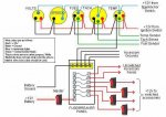
The float is mounted on a rod and both just sorta bob along in the gas, the other side of the rod thou drives a wiper arm of a rheostat inside a sealed area. The rheostat is just a fancy name for a variable resistor to ground who's resistance, due to the float, arm, wiper connections, is varying proportionally with gas levels. When the resistance varies, so does the current in the circuit and the gauge is just secretly a current meter who's needle is just showing current levels......

In out case, "E" equates to low current due to higher resistance and "F" equates to a high current due to low resistance and lots of points in between.

They're actually quite simple and when you grounded the "S" terminal, you created a maximum amount of current to flow in the circuit and the meter(gas gauge) showed that to you as "F ++++".

Hang in there and plz do let me know, we'll win this war :)
 
Last edited:
Top