Re: Carling rocker switch
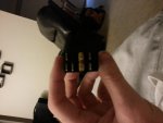
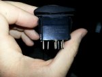
The two center terminals with the bar between them is the +12 volt input (line) from the fuse panel. Since we cannot see the switch numbering we have to rely on your eyes. That switch has only seven terminals although there is room for 8. So the terminal that seems to be all by itself (bottom row - second from left) is probably the ground connection for the internal light. Leave that terminal alone for now.
So this leaves the two terminals on the far left and the two on the far right to deal with. Here is a diagram of the NAV/ANC switch wiring for a NON-LIGHTED switch. Wire the switch as shown in that diagram and see if the lights work properly. Pushing the top of the switch when installed, should turn on both lights. OFF is in the middle, and the stern light only will be on when you push the bottom of the switch. If they work in reverse, simply move the wires on the left to the right side and vice versa. When you have the lights working properly, connect the odd terminal to ground and the internal light should now work. If the wiring described doesn't work you did something wrong, or you need to Google "Carling V series rocker switches" and look at their data sheet for a wiring diagram of the switch. Apply what you found to the diagram I posted. Don't get all wrapped around the axle here. Logic applies.