Fabbe2
Seaman Apprentice
- Joined
- Jun 19, 2011
- Messages
- 36
During my engine testing I discovered that the LED for the rev limiter in the Suzuki monitor gauge was broken. Here are some hints how to replace a damaged LED on this unit:
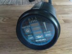
OK i did not expect it to have LEDs but that explains the not user friendly construction.
Looking for a way in I discovered a small notch at the bottom. Carefully getting into it with a carpet knife did remove most of the glue and I managed to open the can without bigger damage:
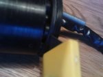
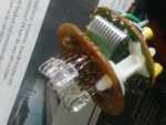
Inside you'll find 2 circuit boards attached with 2 screws. The lower one holding the LEDs and resistors, the higher one holding the elements for the oil level delay:
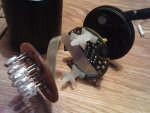
A quick check on the LEDs showed to broken lamps. Rev limit and water temp.
No I had to decide if soldering directly on the circuit board or just to take the LED a bit higher up. I decided for the later version because I thought of further replacements if not using the right LED.
So I cut out the damaged LED:
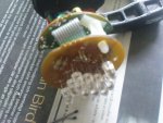
Meanwhile I was checking on a good spare part, knowing the resistors on the upper circuit board to have 474 ohms. Found 5mm LEDs, red, 8'000mcd with 30? which come close to the original ones during testing.
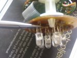
So I cut the connectors to the right length and clamped it to the connections left from the old LED. Polarity was written on the board, anode down, cathode up.

OK i did not expect it to have LEDs but that explains the not user friendly construction.
Looking for a way in I discovered a small notch at the bottom. Carefully getting into it with a carpet knife did remove most of the glue and I managed to open the can without bigger damage:

Inside you'll find 2 circuit boards attached with 2 screws. The lower one holding the LEDs and resistors, the higher one holding the elements for the oil level delay:

A quick check on the LEDs showed to broken lamps. Rev limit and water temp.
No I had to decide if soldering directly on the circuit board or just to take the LED a bit higher up. I decided for the later version because I thought of further replacements if not using the right LED.
So I cut out the damaged LED:

Meanwhile I was checking on a good spare part, knowing the resistors on the upper circuit board to have 474 ohms. Found 5mm LEDs, red, 8'000mcd with 30? which come close to the original ones during testing.
So I cut the connectors to the right length and clamped it to the connections left from the old LED. Polarity was written on the board, anode down, cathode up.


