PLEASE HELP wiring fuse panel with illuminated switches

nightimefishn

Seaman
Joined
Jul 27, 2009
Messages
54
Hi I am having some issues with wiring my new carling illuminated switches.
I have 6 gauge wire directly from battery pos and neg.

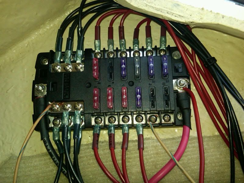
I have wired red 14 gauge from blue sea systems fuse panel positive to the middle terminal on the carling rocker. I have black 14 gauge from ground on the blue sea systems fuse panel to the ground on the carling switch.

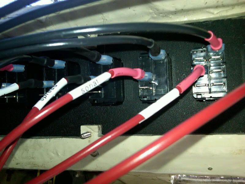
These are simple on / off 3 prong illuminated switches.

Here is my issue
I have 12 volts to the fuse panel tested with meter. Once I flip the switch I lose power to the fuse panel. And the switch does not light up.

My wiring is planned as follows top connection ground to fuse panel 12 volt source. Middle terminal from fuse panel and bottom terminal to the pos on the device I want power to then ground the neg terminal on the device to a ground buss. It works as discussed when connected in my garage directly to a battery without the fuse panel. I am kind of stumped here and could use someone advice. I always find my help on this forum!!!

Attached a couple of pictures of fuse panel and switches.

Thank you very much!

IMG00103-20110403-0910.jpg


IMG00102-20110403-0909.jpg
 

Moody Blue

Captain
Joined
May 24, 2004
Messages
3,136
Re: PLEASE HELP wiring fuse panel with illuminated switches

I've read your post several times but can't get my head around what you describing. From what you are describing and from the second photo, I would guess that you have created a dead short when you activate the switch. There should be a third wire to each of the switches. Three terminal on the switch. Power FROM fuse panel to one terminal. Power TO load to another terminal. Third terminal should grounded. It is important that you identify which of the three terminals is the ground connection for the internal lamp of the switch.

Here is a good visual example of the basic wiring you need.

http://www.bcae1.com/switches.htm

One final comment. Very nice work on the wiring. Looks very professional.
 

LippCJ7

Vice Admiral
Joined
Sep 20, 2010
Messages
5,431
Re: PLEASE HELP wiring fuse panel with illuminated switches

First off your wiring looks great other then the yellow/blue trace and the red on the supply stud I have to hand it to you top notch!

First is I would like the battery voltage as tested between the positive and negative battery post
Battery voltage from battery negative post to supply side of fuse block
Battery voltage from battery negative post to the fused side of the breaker panel
Battery voltage from battery negative post to the switch positive

etc etc keep following the voltage, when it stops you found the problem, if you make it all the way to the load then you switch gears to the ground and test resistance/continuity/ohms and go about it the same way as voltage.
Meter on Ohms
Test resistance from the battery negative post to the ground on the fuse block
test resistance from the battery negative post to the ground on the switch
test resistance from the battery negative post to the ground on the load

This is how I go about finding 12 volt readings, they should be within 1 volt dc of the battery voltage reading, more and you have found an issue, log it and move on, if you find zero volts you have found your problem.
Grounds should be less then 1 ohm again anything more then 1 ohm and you have found an issue log it and move on, in both situations you can revisit the issues you have found and solve them later, when you find more then 1 ohm its a big issue, less then an ohm and just move on its no problem.

It looks like the switches do not have loads hooked up yet in your pictures, get those hooked up I have seen where the switch will not work properly until it is hooked up completely

Let me know what you find!!

Also when I say the post I mean the battery POST not the connector you want the cleanest readings possible!
 

nightimefishn

Seaman
Joined
Jul 27, 2009
Messages
54
Re: PLEASE HELP wiring fuse panel with illuminated switches

Thanks Moody,

You are correct the third terminal the one blank on the picture is going to the positive connection on the load.
I apologize as I pretty sure my terminology is way off.

I think you are right on the dead short but I am not sure why or how. I have looked at the carling instructions and they dont make sense to me.

If I take the switch out and connect it to the battery in my garage it works as follows

I have negative connected to the top terminal as in the picture, positive from battery connected to the middle terminal and it lights up when activated. If I add the pos connection from the load to the third bottom terminal the device powers on. The only variable different on the boat is this fuse panel. But I am almost positive I have it connected properly. I took a look at your link, thank I will try a different connection. I am just stumped why it works in the garage but has totally different behavior on the boat.

Thank you for the compliment on the wiring, I took my time this time around knowing it doesnt pay to rush it. BUT NOW OF COURSE this has me stumped a bit.
 

LippCJ7

Vice Admiral
Joined
Sep 20, 2010
Messages
5,431
Re: PLEASE HELP wiring fuse panel with illuminated switches

Guys if you had a dead short it would have either blown the switch or the fuse, check the continuity of the switches, you could have hooked them up wrong and blown the switch but with 2-4 amp fuses the fuse would have blown first so check there
 

nightimefishn

Seaman
Joined
Jul 27, 2009
Messages
54
Re: PLEASE HELP wiring fuse panel with illuminated switches

Thanks for all the suggestions. I will start checking what you told me to. I dont think the switches are blown because if I take the same switch out and test in my garage it works fine as it should. I am leaning towards this fuse panel. It is the only thing different with this setup. I must be hooking up something incorrectly or in the wrong order. I get 12 volts between all terminals at the fuse panel.

I get 0 volts as soon as any switch is turned on, I am sure its something stupid. I am tempted to take the panel out of the boat and wire the circuits in the garage and see if I can figure it out.
 

nightimefishn

Seaman
Joined
Jul 27, 2009
Messages
54
Re: PLEASE HELP wiring fuse panel with illuminated switches

First off your wiring looks great other then the yellow/blue trace and the red on the supply stud I have to hand it to you top notch!

First is I would like the battery voltage as tested between the positive and negative battery post
Battery voltage from battery negative post to supply side of fuse block
Battery voltage from battery negative post to the fused side of the breaker panel
Battery voltage from battery negative post to the switch positive

etc etc keep following the voltage, when it stops you found the problem, if you make it all the way to the load then you switch gears to the ground and test resistance/continuity/ohms and go about it the same way as voltage.
Meter on Ohms
Test resistance from the battery negative post to the ground on the fuse block
test resistance from the battery negative post to the ground on the switch
test resistance from the battery negative post to the ground on the load

This is how I go about finding 12 volt readings, they should be within 1 volt dc of the battery voltage reading, more and you have found an issue, log it and move on, if you find zero volts you have found your problem.
Grounds should be less then 1 ohm again anything more then 1 ohm and you have found an issue log it and move on, in both situations you can revisit the issues you have found and solve them later, when you find more then 1 ohm its a big issue, less then an ohm and just move on its no problem.

It looks like the switches do not have loads hooked up yet in your pictures, get those hooked up I have seen where the switch will not work properly until it is hooked up completely

Let me know what you find!!

Also when I say the post I mean the battery POST not the connector you want the cleanest readings possible!

The blue/yellow trace were just soem test wires I had going. Every wire is connected with heat shrink connectors and or heat shrink tube for the disconnects.

Thanks again for the compliment.
 

Silvertip

Supreme Mariner
Joined
Sep 22, 2003
Messages
28,762
Re: PLEASE HELP wiring fuse panel with illuminated switches

I also appreciate neat wiring. A bit overkill on wire size but nice job. I say that only because the largest fuse I see is 4 amps so 16 gauge would have been perfectly adequate. Wire sizes don't need to be consistent for all circuits. Wire size is selected for the current being consumed by the load. Also, 14 gauge wire to service the bulb in the switch was way overkill. But -- it's done and it should work. Now to the problem. Flipping any switch or combination of them cannot be due to a short because the fuses are ahead of the switch. Therefore a short would pop the fuse. Since you have 6 gauge wire protected by a circuit breaker at the battery, a weak breaker is also not the problem since it would have to open with less current draw than the lowest rating of any of the fuses. The trick here is to flip a switch and then work backwards checking for voltage at the switch, at the panel, after and then ahead of the fuse, then to the 6 gauge wire and back to the breaker. Somewhere along the line is the problem.

Are you absolutely certain you have +12 volts connected to the LINE side of the switch and not the LOAD side of the switch. This doesn't make any difference on a NON-lighted switch but on a LIGHTED switch it does. The tip off would be that the indicator light would be ON with the switch in what you think is the OFF position (essentially making the switch work backwards). Try this: disconnect the indicator light ground at the switch. Flip the switch on and off. The light should not work. Now check for voltage on the LOAD terminal. Still no voltage work backwards until you find it. But make sure you have the correct LINE and load terminals. Remember, if you put +12 volts on the indicator ground terminal the light will still work ok but that means you have the ground for the light on the wrong terminal as well.
 

nightimefishn

Seaman
Joined
Jul 27, 2009
Messages
54
Re: PLEASE HELP wiring fuse panel with illuminated switches

Guys can you confirm this is correct


Red + from battery to positive on fuse panel
Black - from battery to neg on fuse panel

Red + from fuse panel to switch
Red + from load to switch

Black - from switch to fuse panel ground bus

Black - on device(load) to - grounding bus

Illuminated V Series Carling Rockers SPST switches
 

nightimefishn

Seaman
Joined
Jul 27, 2009
Messages
54
Re: PLEASE HELP wiring fuse panel with illuminated switches

Thanks Silvertip I will triple check again but I am almost certain I have everything connected correctly. I ran in to that issue when testing and figured that out with the light staying on. So switched them around until I had it working properly.

I will test backwards as you suggested.

Also no breaker from the battery for now connected directly to the pos and neg battery terminals.

Thanks
 

LippCJ7

Vice Admiral
Joined
Sep 20, 2010
Messages
5,431
Re: PLEASE HELP wiring fuse panel with illuminated switches

Make sure you check your fuses with a meter, the small size of the fuses 2-5 amp could be blown while visually they may look fine, just a little food for thought, bigger fuses 15/20/25 amp go big when they blow so there is no mistaking a bad fuse there

You said initially:
I have 12 volts to the fuse panel tested with meter. Once I flip the switch I lose power to the fuse panel. And the switch does not light up.

do you mean you lose all power to the fuse block when you flip a switch?

Does anything work off this fuse block?

I have found the Fuse block technical specs online but do you have a model number of the Carling switch so that I can look that up as well?
 

Silvertip

Supreme Mariner
Joined
Sep 22, 2003
Messages
28,762
Re: PLEASE HELP wiring fuse panel with illuminated switches

From what I can gather -- the only load on this entire system is the bulb for the switch illumination. That draws so little current it cannot possibly pop a fuse of the size in this panel. A dead short somewhere with no breaker would bring smoke and flames. What does that leave?? Battery and poor or incorrect connections. If you are so certain you have it wired correctly, then it should work so something is not right. Look at the switch on the left (fourth from the right). Why is it I see a red wire at the top terminal whereas you have black wires in that position on the other switches?
 

LippCJ7

Vice Admiral
Joined
Sep 20, 2010
Messages
5,431
Re: PLEASE HELP wiring fuse panel with illuminated switches

Silvertip, I think that red wire is actually red heat shrink on a black wire, I agree with everything else though something just isn't right, I keep wondering if the battery has anything other then float voltage in it but even float voltage would glow a light, slim chance but this just doesn't sound right
 

nightimefishn

Seaman
Joined
Jul 27, 2009
Messages
54
Re: PLEASE HELP wiring fuse panel with illuminated switches

Thanks for all the replies. The fourth switch is actually black wire on top with red heat shrink(i had tun out of the black and bought a roll of red.)

You are correct, the only load at this time is the indicator light. I had tried connecting the courtesy lights but with the indicator light not working I knew something was wrong and stopped there.

Yes when i test my fuse panel on the pos and neg battery in terminals I get 11.97 volts. When I put my meter on each each fuse I get 11.97 volts. As soon as I flip ANY switch I get o volts ANYWHERE on the fuse panel. I will look up the carling switch number I bought them from genuine dealz. Needed to attend a wake today so couldnt work on it more. Hoping I can get out there again tomorrow afternoon.

This is my second battery for just running electronics etc. I have to be missing something. Once I get some more time I am going to go out with my meter and star looking at everything again and follow all the instructions. I tested the battery and get 12 11.98 volts at the battery. I will get at is again as soon as possible. If it wasnt so cold here in NY right now I'd be out there with some halogens burning the midnight oil. ONly have a few weeks before I drop the boat in the water.

Thanks again everyone for all of your help. Very much appreciated. I know it must be something stupid Im missing. But will figure this out !!!!
 

Silvertip

Supreme Mariner
Joined
Sep 22, 2003
Messages
28,762
Re: PLEASE HELP wiring fuse panel with illuminated switches

If you are measuring Zero volts anywhere on the fuse panel when you flip a switch, then measure voltage AT THE BATTERY at the same time. I'm still betting you have a bad battery or a bad connection at that battery. Just because it measures 12 volts does not mean its a good battery. It simply cannot deliver current. Do the obvious things first. VERIFY that this is a good battery by charging it and then having it load tested. And once again -- what are the two tan wires with the stripe? They are connected to a positive and negative feed so that does represent a load of some sort.
 

nightimefishn

Seaman
Joined
Jul 27, 2009
Messages
54
Re: PLEASE HELP wiring fuse panel with illuminated switches

Thanks again Silvertip. I just went out and tried a couple things. Same result when switching wiring around a little bit.
So heres what Ive done
I brought the fuse panel 2 switches in my garage and wired them up the same way they are on the boat to a known good fully charged battery. All works just fine.
I went out and go the second battery and when I connected to the charger it says 30%. So I think you are right, my mistake was thinking that since I was getting 12 volts that it was ok. Rookie mistake! I am charging the battery now, and will see in the morning. Where would I go about load testing? Can I take it to an auto store like pep boys or something? I'd rather not go to West marine, 9 out of ten times it is someone there that doesnt know too much just working the counter.

The two tan wires were just some testing wires when I was testing courtesy lights I was running. I have removed them. They were just connected for testing and when I took the picture I happened to be just finishing up.

Thanks again for everyone's help I really do appreciate it!!

I will let you know once I get this straightened out.
 

LippCJ7

Vice Admiral
Joined
Sep 20, 2010
Messages
5,431
Re: PLEASE HELP wiring fuse panel with illuminated switches

Yes autozone pep boys they can all load test your battery
 

nightimefishn

Seaman
Joined
Jul 27, 2009
Messages
54
Re: PLEASE HELP wiring fuse panel with illuminated switches

Ok I want to apologize for taking up everyones time!!!

I charged the battery and wired everything back up. The whole panel is now working correctly. I really appreciate everyones help and advice with this one! I was under the impression that since I had 12 volts at the battery and the fuse panel that it must have been something else I was doing wrong.

Really thanks all, I am sure I will have some more questions about the rest of the work I have to do with this boat.

Happy boating/fishing to all!
 

objohn22

Recruit
Joined
Apr 4, 2011
Messages
4
Re: PLEASE HELP wiring fuse panel with illuminated switches

I have the exact same switches on my Hurricane, and every one of the illuminated switches have three wires! Hot, Load and Ground. I am puzzled with your pics. I see they are each labled, indicating they must be the load side or the leads going to each device. That would also make since why they do not light up. If that is the case, where is your power lead or hot wire to each switch? It is impossible to complete or close the circuit to send power to your device the way I see it. The third wire (or black) is the ground that allows the light to work. If they were not illuminated swiches, you would not even have the balck wire there. Not an expert, just been there done that with these same switches.
 

nightimefishn

Seaman
Joined
Jul 27, 2009
Messages
54
Re: PLEASE HELP wiring fuse panel with illuminated switches

I wanted to label the wires at the switch so I knew which one was which coming from the fuse panel. Both ends are labeled.

Thanks for your reply. The loads were not connected yet, I have since connected the loads and everything is working well now.

Thanks for the reply.
 
Top