Auto bilge switch question

zonaman

Petty Officer 2nd Class
Joined
Apr 1, 2005
Messages
118
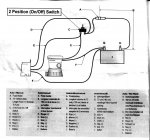
Need some advice wiring an auto bilge switch (refer to attached diagram). The Attwood folks have the brown wire (E) going to the on/off switch (C) on the bilge pump side and the red wire (D) going to the on/off switch on the fuse/power side. That's about 13 feet for each color wire to connect just as the diagram shows. What I would like to know is if I can splice the auto bilge switch into 1. the brown wire any where between the pump and the bilge side of the on/off switch and 2. connect the red wire anywhere between the on/off switch and the fuse?. It would save me several feet of wire if I can.

One more thing, my fuse is longer than the 72" recommended from the battery, it's more like 120" though I'm using 14 awg wire.

Thanks.
 

Attachments

  • Bilge Switch.jpg
    Bilge Switch.jpg
    147.6 KB · Views: 6

NYBo

Admiral
Joined
Oct 23, 2008
Messages
7,107
Re: Auto bilge switch question

You can tap the brown wire to the pump anywhere you'd like. Since my battery, bilge pump, and float switch are in the stern, and the manual switch is at the helm, I ran a separate fuseholder-equipped line directly between the positive terminal of the battery and one of the float switch wires (mine has only 2 wires); the other wire from the float switch taps into the brown wire from the pump right near the pump. The splice is supported up above the bilge so it doesn't get wet.
 

fishrdan

Admiral
Joined
Jan 25, 2008
Messages
6,989
Re: Auto bilge switch question

That diagram will get the job done, but WOW, it's going about wiring the long way.

It's easiest to think of it as 2 separate systems (switched and auto switched) that are combined at the bilge pump.

1- Run your float switch to the battery with a fuse holder close to the battery. (FYI, the fuse holder should be within 12" of the battery, the closer the better)
2- Run your manual switch wiring back to the bilge pump (fused at the boat's fuse panel).
3- Connect both the float switch wire and manual switch wire to the bilge pump's + wire.

- if the water rises in the bilge the auto switch will turn on
- if you flip the manual switch the bilge pump will tun on

The only thing you are adding outside of the diagram is an additional fuse, to protect the "other" positive wire for the bilge pump.

I think this is the same thing NYBo was saying and he has some good tips in his post too.
 

dingbat

Supreme Mariner
Joined
Nov 20, 2001
Messages
15,481
Re: Auto bilge switch question

Both of my blige pumps are wired like the diagram.

They run the power thru the switch to light the LED. If the bilge comes on in auto mode you know about it. Nice to know you have a problem before you have water on on the deck. I know several people who went as far as to wire a buzzer into the circuit.
 

NYBo

Admiral
Joined
Oct 23, 2008
Messages
7,107
Re: Auto bilge switch question

The way fishrdan and I described it will also light the indicator in the panel switch. That's how mine works.
 

zonaman

Petty Officer 2nd Class
Joined
Apr 1, 2005
Messages
118
Re: Auto bilge switch question

Both of my blige pumps are wired like the diagram.

They run the power thru the switch to light the LED. If the bilge comes on in auto mode you know about it. Nice to know you have a problem before you have water on on the deck. I know several people who went as far as to wire a buzzer into the circuit.

Thank you all for your responses.

I like the idea of an indicator light or buzzer. My switch is not lighted. I presume the light or buzzer would need to be added on the brown wire (E) that leads from the on/off switch to the pump, correct?
 

seabob4

Lieutenant Commander
Joined
Jun 10, 2008
Messages
1,603
Re: Auto bilge switch question

Thank you all for your responses.

I like the idea of an indicator light or buzzer. My switch is not lighted. I presume the light or buzzer would need to be added on the brown wire (E) that leads from the on/off switch to the pump, correct?

Correct. The brown wire, when energized by either the switch at the helm or by the float switch, is the pumps 12V+ feed, in other words, what turns the pump on. Therefore, the audible/visual warning needs to be spliced into the brown wire...and you can pick up the ground that device will need from the nearest ground source...
 

zonaman

Petty Officer 2nd Class
Joined
Apr 1, 2005
Messages
118
Re: Auto bilge switch question

I like fishrdan's wiring scheme but I have one question- The switch is not a float type, it is an Attwood S3 (http://www.attwoodmarine.com/store/product/digital-bilge-switch---s3-series) that uses sensors. It runs for several seconds when switched on then shuts down if the sensors are not wet for more than 8 seconds. Fishrdan's wiring will have that S3 "hot" at all times. Might that adversely effect it's operation?
 

seabob4

Lieutenant Commander
Joined
Jun 10, 2008
Messages
1,603
Re: Auto bilge switch question

Look at the diagram YOU posted. H, coming off the batt 12V+ goes to one side of the on/off switch (used to power the switch), and the lead from the float you want to use goes to the same terminal. This IS wired constant hot...the way it's supposed to be.
 
Top