


Greetings to the list,
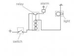
I am an instructor at a trade school specializing in marine systems. I am looking for a relatively simple wiring diagram that would include LED indicator lights and an alarm function for a standard navigation light circuit. Any and all help would be appreciated.
I am an instructor at a trade school specializing in marine systems. I am looking for a relatively simple wiring diagram that would include LED indicator lights and an alarm function for a standard navigation light circuit. Any and all help would be appreciated.


 ..Good for you....I am interested as well.
