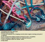
Anyone explain this ammeter to ignition link?

badman

Petty Officer 2nd Class
Joined
Dec 29, 2008
Messages
117
Hi there boater type folks.
Gotta electrical issue here that we can't figure out.
The wiring loom in my boat includes an ammeter on the dash board. Fine.
The alternator sends current up to the amp meter via a decent sized cable (4mm) whilst another decent sized cable returns from the second post of the amp meter back to the engine bay where it connects to the positive terminal of the battery.
This all seems above board as the amp meter has to be 'in line' between the charging source and the battery to give a valid readout.

Another decent sized wire runs from the positive terminal of the battery up to the dash where it terminates at post 1 of the ignition switch (3 pole).

The ignition switch has switched electrics on pole 2 and the starter motor on a sprung return 3rd pole.
what i can't understand is there is a fused link between the live terminal of the amp meter and pole 2 of the ignition switch (for switched electrics).
This would make a second link between the charging alternator current and the battery current, even though the battery current is already present and is topped up by the alternator via its amp meter loop.
image is attached with text and two larger images can be found at:
http://www.tribidium.com/matt/boatpics.html

thanks
 

Attachments

  • Wiring-amp-meter-dash.jpg
    Wiring-amp-meter-dash.jpg
    21.5 KB · Views: 0

a70eliminator

Captain
Joined
Sep 9, 2007
Messages
3,694
Re: Anyone explain this ammeter to ignition link?

Well since nobody else replied yet I'll give it a shot.
Very informative photos by the way.
I believe that is whats called a shunt (bypass) it's creates a path for the charging current so the ammeter doesn't have to carry 100% of the load, I think?
 

JB

Honorary Moderator Emeritus
Joined
Mar 25, 2001
Messages
45,907
Re: Anyone explain this ammeter to ignition link?

The ammeter should carry all current except the starter and PT&T, if so equipped. That way it can show if any, and how much, current is going into the battery or how much is being drained.

I read your post several times and it seems, like the eliminator said, that you have shunted some current around the ammeter so it is giving inaccurate readings.
 

Mark42

Fleet Admiral
Joined
Oct 8, 2003
Messages
9,334
Re: Anyone explain this ammeter to ignition link?

Moving the fused wire (shunt) to the other terminal on the ammeter will include the ignition registering on the gauge. Before doing that, you should check to be sure the gauge can handle the load. It may just be there to show if the battery is charging or not.
 

a70eliminator

Captain
Joined
Sep 9, 2007
Messages
3,694
Re: Anyone explain this ammeter to ignition link?

be very cautious about changing anything, what appears to be a fuse holder may be a resister matched to the ammeter's load capabilty, open it up and see.
 

JorgeE

Seaman
Joined
Mar 21, 2008
Messages
51
Re: Anyone explain this ammeter to ignition link?

Badman, doesn't make sense...
first point: Seems that circuits that normally would be switched are powered all the time since wire D is by passing the ignition switch, and providing battery power directly... are you having trouble with battery going dead?
Second point: Since wore D provides battery power to common on ignition switch, the ammeter is not (as someone else already pointed out) reading all the current that is coming out of the battery. Does this wire look like it is an OE wire, or might it have been added sometime in the boat's life after it left the factory?
Would make more sense if wire D did not exist, and wire C went from ammeter to ignition switch common terminal. In this way, all current coming from battery would go through ammeter, and "switched" circuits would all be in fact switched.
Couple of questions: How large is C wire? large enough to carry current in switchede circuits? How large is the fuse in wire C? enough to handle demandes of switched circuits?
By the way... personal opinion is that ammeters are a far second to voltmeters to indicate charging system performance. Voltmeter is MUCH more useful in detecting problems before they can cause damage (ie: to battery or other electrical items). They also are safer since wiring doesn't have to carry so much current, and can be fused at low currents (less than 1 AmP), and they are simpler since only one wire is needed fomr battery to meter, the other can be grounde under dash. On our old boat, I replaced it with a voltmeter.
Hope this helps; hopefully we can get to the bottom of this.
Jorge
 

fishrdan

Admiral
Joined
Jan 25, 2008
Messages
6,989
Re: Anyone explain this ammeter to ignition link?

It looks like they are just using the terminal on the ammeter with the (A) and (C) wire as a post to tie these 2 wires together. All the current for the accessories and engine ignition go through the ammeter. I looked at the dash off my old 72 Mercruiser (cause it's sitting on the work bench :D) and there is no shunt on the 40 amp ammeter, but they tied all sorts of crimp connectors onto the ammeter electrical post, just a way to make an electrical connection.

On my ammeter fuses, gauges, ignition switch (and I assume it's the alternator wire) are tied to a common post, and the battery post has the battery wire and the "accessory" switch/fuse tied to it. Come to think of it, I always wondered why the ammeter didn't spike when I flipped on my 1 jillion candle power spot light, it wasn't going through the ammeter.

I'm guessing the holder on wire (C) is a fuse holder.

That's just how it was done on my old boat, hope it helps.
 

badman

Petty Officer 2nd Class
Joined
Dec 29, 2008
Messages
117
Re: Anyone explain this ammeter to ignition link?

hey thanks y'all for the many replies.
Will have a look at the fuse today to see what rating it is.
One thing i really don't get is... the ignition switch needs battery power to start the engine.
Without the engine started, there is no charging current. So there has to be a supply to the ignition switch from the battery. Whether or not this should go through the ammeter i don't know. Need another coffee to work that one out!
Will consider all of your great replies and see if i can make more sense of it..

I cetainly agree that i looks like switched electrics are indeed not switched but on all the time as they are paired up with the battery supply.. that chunky red wire. A very easy way to drain the battery.
Also, the tilt wiring seems to come off the alternator power too.. Very silly because in positioning the boat in and out of the water a bit of tilit would be very handy and the engine would never be running.

Starting to make me think that some of the wires are not charging and battery, perhaps the pother way round?
Shame they are all loose in the rear bay and not labelled!
Arghh!
:)
 

JorgeE

Seaman
Joined
Mar 21, 2008
Messages
51
Re: Anyone explain this ammeter to ignition link?

Hey Badman,
I think my head is spinning a little. Just some more comments...
Until the generator starts producing current, anything electric will run off the battery, and you would want that current to go through the ammmeter - this is one of hte main purposes for it, to tell you whether your'e putting in, or taking out current from the battery. You are correct, the ignition switch must get power from the battery, but the ammeter is a very low resistance device and the power to the ignition switch should go through it, essentiall the two sides of the ammeter are shorted together.
The Tilt may be one exception to the above for two reasons: 1- It may draw excessive current for the ammeter; 2- It is a momentary load, and wouldn't really tell you how the charging system is performing. On my boat, the tilt/trim wire goes directly from the battery to the pump/motor (through fuse of course).
Did you come to any conclusion on whether "D" wire is OE?
Heppy hunting!

Jorge
 
Top