Unravelling someone else's "creative" gauge wiring.

cheburashka

Senior Chief Petty Officer
Joined
May 28, 2005
Messages
715
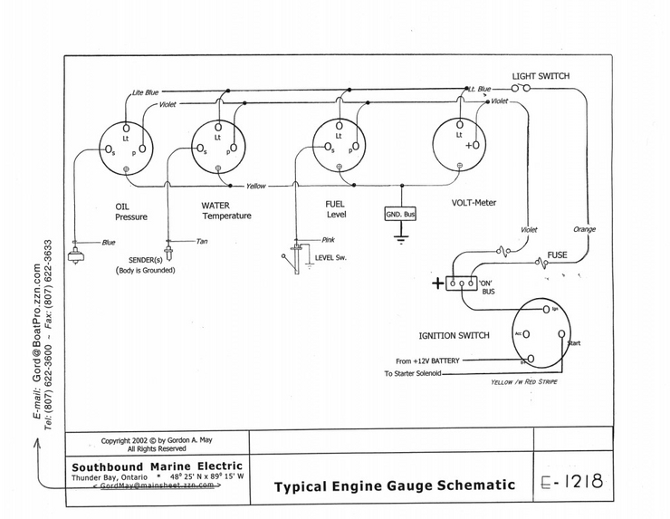
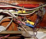
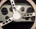
I'm working on a '74 Glassply, Mercruiser 140 i/o. The gauges are pretty simple, but someone in the past rewired them with single-strand telephone wire, and it's starting to get brittle and snap in places. There are all kinds of voltage draws, minor shorts, etc. The problem is, I don't know what the wiring looked like in the first place. So my questions are:

What gauge wiring was used in the first place?

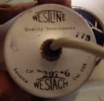
There are really fat resistors soldered into the system for each gauge, and I'm not sure if they were originally there when the boat was built.

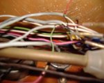
What originally came out of the backs of the gauges? Right now it's gray four-strand telephone cable, which doesn't look right at all.

Should I hard-wire the whole thing, or is it best to use connector blocks and bullet connectors to aid in trouble-shooting?

Finally, why the heck would anyone even do this to a boat?

I plan to to re-do this by soldering the connections and using heat-shrink tubing, replacing each connection one at a time. Any tips or hints?

Thanks
 

cheburashka

Senior Chief Petty Officer
Joined
May 28, 2005
Messages
715
Re: Unravelling someone else's "creative" gauge wiring.

Now I'm even more confused. I removed the fuel gauge. It's made by "Westline." The problem I'm having now is that the gray four-strand wires come straight out of the back of the gauge and can't be accessed. Is it possible that the single-strand telephone wire is stock? Doesn't seem right to me, but I can't see any other way it could have worked.
 

KnottyBuoyz

Senior Chief Petty Officer
Joined
Mar 6, 2006
Messages
712
Re: Unravelling someone else's "creative" gauge wiring.

I feel your pain and can relate totally! I had a similar mess (and still working out the gremlins) on our boat. I've probably got 300 hours in wire tracing & replacement over the past 4 yrs. I've probably replaced 1000' of wire in a 25' boat! *lol* Everything from 2/0 ga battery cables to 24 ga CANet network wiring.

You might try some of the websites for guage manufacturers if you know what brand yours are. They may have wiring diagrams online. I found mine and it helped alot.

DO NOT and I repeat DO NOT just yank everything out! Don't ask me why I said that! ;-) Tracing wires is a pain in the you know what but in the long run it'll be worth it. Get some masking tape and a sharpie marker to label what you can identify. Using old wiring to pull in new is sometimes a lot of help. A 12 volt test light and volt meter are also a must.

I think most guages would be wired with 16-18 ga wire. I'd opt for the tinned marine variety if cost isn't an issue. Double crimp ratcheting tool is a must and believe me makes the job a whole lot easier. Soldering is ok in some situations but if you want to follow standards it shouldn't be the only form of splicing wires. I set up a bus with a terminal strip under the dash to pass through all connections w/o having to resort to crimp connections and soldering. The crimp-on J-hook connectors work great and save a lot of fiddling with tiny screws.

Most marine wiring is color coded. If you plan to keep this boat or add some value to it you might consider following the standard colors.

Here are some diagrams that might help get you started.

WiringDiagrams-ELEC-D4.gif


WIRINGDIAGRAMS-ELEC-D3.gif


79gaugetest1-med.jpg


Good luck with your project. Just holler if you need help.
 

cheburashka

Senior Chief Petty Officer
Joined
May 28, 2005
Messages
715
Re: Unravelling someone else's "creative" gauge wiring.

The actual wiring doesn't phase me. It's just looking at that single-strand wiring and wondering if that's what was originally there, and if not, how the heck did they get it inside of those sealed instrument housings? I'm beginning to think that this is the stock wiring--aside from the plastic butt splices and the electrical tape.
 

JCF350

Lieutenant Junior Grade
Joined
Oct 21, 2007
Messages
1,149
Re: Unravelling someone else's "creative" gauge wiring.

You can find creative anything in boats. Sounds like someone using lower power gauges (since there are resistors on them). Some pics would be interesting to look at, but I would start from scratch with gauges and wiring.
 

cheburashka

Senior Chief Petty Officer
Joined
May 28, 2005
Messages
715
Re: Unravelling someone else's "creative" gauge wiring.

You can find creative anything in boats. Sounds like someone using lower power gauges (since there are resistors on them). Some pics would be interesting to look at, but I would start from scratch with gauges and wiring.

They appear to be the stock gauges. They're made by Westach and they have drawings of little boat-style steering wheels on them.
 

Attachments

  • Westach 2.JPG
    Westach 2.JPG
    49.6 KB · Views: 0
  • Westach 3.JPG
    Westach 3.JPG
    25.7 KB · Views: 0
  • Westach 4.JPG
    Westach 4.JPG
    18 KB · Views: 0
  • Westach 5.JPG
    Westach 5.JPG
    57.2 KB · Views: 0

JCF350

Lieutenant Junior Grade
Joined
Oct 21, 2007
Messages
1,149
Re: Unravelling someone else's "creative" gauge wiring.

Looks like a telephone guy has run AMOK!:mad:

You can go here and maybe find something on the gauges:)
http://www.westach.com/

Are the resistors connected to sending unit terminals or to the light for the gauge?
 

jtexas

Fleet Admiral
Joined
Oct 13, 2003
Messages
8,646
Re: Unravelling someone else's "creative" gauge wiring.

rewiring your boat is a real labor of love....but there's way worse ways to spend an afternoon. I pulled miles of wire that weren't even connected to anything!

answer your question...single strand wire is a bad idea and wouldn't be done by anybody who knows anything. ABYC standard is marine grade tinned copper strand. I used automotive (fresh water only). I can already tell it won't last as long as the tinned wire. Crimp, or crimp and solder; solder should not be the sole means of connection. Wire nuts are out.

have fun!
 
Top