Accessory Panel Power

Mlbrowne

Cadet
Joined
Dec 13, 2017
Messages
8
Hello everyone! New to the forum and to boating!

I recently got a used 2007 Harbercraft (jetcraft). Everything works great except the entire accessory panel has no power. I do not know if I am calling it the correct thing, but the factory switch board that has Nav lights, bulge, horn etc is not working. I have power to the control, steering, tax and everything else, but nothing on that switch board.

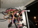
I went under the dash and there are two wires that seem to be disconnected, but no obvious home for them. I was hoping someone with some knowledge could help me out. Attached is what I am looking at, one of the loose red wires is labeled ?main?.

The only open spot on the fuse area on the back of the panel is the bottom left on as you look at the photo.


Thanks for any help you could provide!
 

GA_Boater

Honorary Moderator Emeritus
Joined
May 24, 2011
Messages
49,038
Welcome aboard.

You need 3 posts as a new member before the photo restriction is lifted. On your 4th post, start adding pics.

Click on the Forum Help link in my sig for photo posting help. Don't use Photobucket to host your pics.

It does sound like the power feed to the panel is missing of disconnected. Once you can add pics, we can figure it out with you.
 

Mlbrowne

Cadet
Joined
Dec 13, 2017
Messages
8
So based on the orientation of the below photo, the two loose wires (one looks broke off), and the open port on the panel are on the top right corner of the photo.
 

Mlbrowne

Cadet
Joined
Dec 13, 2017
Messages
8
No luck uploading another photo, the other wire that is loose is the red one that is pointing to the one o clock position. It does not look broken, but just lose and not sure where it's home is. I looks like it may connect to the gap on the fuse panel side, but i am not sure where the "main" red line goes.
 
Last edited:

Silvertip

Supreme Mariner
Joined
Sep 22, 2003
Messages
28,762
That red wire is the feed (12 volt IN) to the switch panel. All of the switches are then daisy-chainbed from one to the next. That wire needs to connect to the +12 volt source (wherever that is) . A voltmeter is your friend. Just because there are what appears to be disconnected (white) connectors does not mean they MUST be connected. They may be used on some boats and not on others depending on equipment. I do see the black fuse holder in the red wire at the bottom center of the picture but appears to be a "load" (12 volt out) rather than a "line" (feed). The other red wire is large enough to serve as a feed but from the picture I can't tell where it goes. For sure though, nothing operated by the switches will work with that wire disconnected.
 

Mlbrowne

Cadet
Joined
Dec 13, 2017
Messages
8
Silver tip, thank you so much! You are talking the red wire with the ?main? label, the one that looks to have snapped off metal attached? Is that the one you are describing? I will go see if I can find a spot it was supposed to reach to.
 

Grub54891

Vice Admiral
Joined
Jun 17, 2012
Messages
5,911
This is just a guess, It looks as if that orange wire on the top right should be moved down one hole, so it's in line with the other orange wires. Now the main, that is snapped off would go in the hole where the orange one was, but it must be daisy chained just like the rest in that top row. Notice the different connector on the one red wire, someone tried to fix it without success. Test the main wire before doing anything to see if there is power there. Then use fused test leads to temporarily hook it up to see what works and what don't. Good luck!
 

Scott Danforth

Grumpy Vintage Moderator still playing with boats
Staff member
Joined
Jul 23, 2011
Messages
47,496
this is where a good understanding of DC electrical systems and a multi-meter are your friend [h=2]American Boat and Yacht Council Standards[/h]
BlackGroundNegative / Neutral Main Return
Blue-StripeTilt up and or trim outTilt and or trim circuits
BrownAlternator Charge LightGenerator Terminal or Alternator Auxiliary Terminal to Regulator
Generator ArmatureGenerator Armature to Regulator
PumpsCircuit Breaker or Switch to Pumps
Brown w/YellowBilge BlowersCircuit Breaker or Switch to Blower
Dark BlueCabin & InstrumentCircuit Breaker or Switch to Lights
Green or Green w/Yellow StripeBonding SystemGrounding Wires (if insulated)
Green StripeTilt down and/or trim inTilt and or trim circuits
GreyNavigation LightsCircuit Breaker or Switch to Lights
TachometerTachometer Sender to Gauge
Lt. BlueOil PressureOil Pressure Sender to Gauge
OrangeAccessory FeedAmmeter to Alternator or Generator
Common FeedDistribution Panel to Accessory Switch
FeedAccessory Circuit Breakers or Switches
PinkFuel GaugeFuel Gauge Sender to Gauge
PurpleIgnitionIgnition Switch to Coil & Electrical Instrument
Instrument FeedDistribution Panel Electrical Instruments
RedInstrument FeedDistribution Panel to Electrical Instruments
Power FeedsPositive Main Power (particularly un-fused)
TanWater temperatureWater temperature sender to gauge
YellowGenerator FieldGenerator to Regulator Field Terminal
GroundNegative / Neutral Main Return
Yellow w/RedStarting CircuitStarting Switch to Solenoid

COLOR ITEM USE
 

dennis461

Chief Petty Officer
Joined
Aug 11, 2011
Messages
516
Can you show us the front of the panel and perhaps a make/model number?
 
Top