new boat wiring nightmare......HELP!

winterhawk78

Seaman
Joined
Jun 20, 2017
Messages
51
I just recently bought a 94 Sprint 286 DC Pro Tournament bass boat. And this thing has wires running everywhere. The switch panel that has all the toggles. Does anyone have or can point me in the right place for a wiring diagram or shed some sort of light on that. The main power toggle works, the nav light toggle works, but the toggle marked aerator only works switched to manual, auto does not work. the livewell recirc/ pump out toggle is gone and the bilge as far as I can tell doesn't work. Can someone anyone please help me with this with pictures, diagrams, or vidoes. Also the speedo doesn't work. And we wont talk about the spider webbed battery compartment just yet.
 

winterhawk78

Seaman
Joined
Jun 20, 2017
Messages
51
No Title

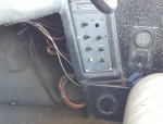
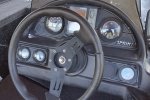
here is a picture of the switch panel and instrument cluster
 

Attachments

  • photo268939.jpg
    photo268939.jpg
    295.8 KB · Views: 0
  • photo268940.jpg
    photo268940.jpg
    228.9 KB · Views: 0

MH Hawker

Vice Admiral
Joined
Jul 13, 2011
Messages
5,516
very few boat makers have any sort of prints, and it looks like a friend and a 6 pack was involved in the past wiring jobs so a print wouldnt be of much use, how ever boat wiring is mostly simple

a boats wiring is 2 separate systems joined at the battery and that often confuses a lot
 

ajgraz

Lieutenant Commander
Joined
Mar 1, 2010
Messages
1,858
How do you feel about a total rewire? Because I suspect that's here you're headed.
 

winterhawk78

Seaman
Joined
Jun 20, 2017
Messages
51
very few boat makers have any sort of prints, and it looks like a friend and a 6 pack was involved in the past wiring jobs so a print wouldnt be of much use, how ever boat wiring is mostly simple

a boats wiring is 2 separate systems joined at the battery and that often confuses a lot

what are the 2 separate systems? Can you explain alittle on that?
 

winterhawk78

Seaman
Joined
Jun 20, 2017
Messages
51
How do you feel about a total rewire? Because I suspect that's here you're headed.

that's what I was thinking. I wouldn't be scared. I just need to know how to hook everything up. exp... on the 24v system for the trolling motor? does it have to have a circuit breaker or can it just have a fuse on the positive side? And what size? 71# thrust motorguide. and on my 3 bank charger, do both leads from each bank need a fuse or just the positive side?
 

Silvertip

Supreme Mariner
Joined
Sep 22, 2003
Messages
28,762
You don't have "two" electrical systems on your boat. You actually have "three". 1) The engine electrical system is fed by the large battery cables that run from the battery to the engine. That system breaks down to several circuits that run up front to the controls, the instrument panel gauges and the engine ignition system and alarms. 2) At the battery there should be a smaller pair of #8 or #10 wires that again runs to the helm to power the switches and the circuits they control as well as other accessory circuits. 3) Your trolling motor batteries are a totally separate system and should not be tied into the engine electrical system.

For the trolling motor, we need to know if it is a combination 12 AND 24 volt motor or 24 volt only. How is the boat currently wired for a troller? Is there a receptacle at the bow and how many terminals in that receptacle. There are a couple ways to do this and it involves either a two or four wire system. A two wire system as the positive of one battery connected to the negative terminal on the second battery. The remaining positive and negative terminals have wires that run to the receptacle at the bow. A four wire system has two wires running from each battery to a four terminal receptacle at the bow. A special four terminal plug with a jumper inside handles the 24 jumper that would normally be at the batteries in a two wire system. Yes, you need a circuit breaker in the positive lead. That should be a 50 - 60 amp breaker depending on the size of the trolling motor. If you use a four wire system, you need a breaker in both positive leads.

Wiring the helm (boat system) the main #8 or #10 feed from the battery feeds the INPUT to a fuse or circuit breaker panel. This lead needs a 20 or 30 amp breaker within a foot of the battery. Each circuit from the fuse panel is then fused according. You always want a fuse in any branch circuit and you do NOT fuse the negative lead. 16 gauge wire is adequate for nearly every branch circuit on the boat except for high power stereo systems or other high current draw items.

When wiring the gauges, each terminal on each gauge is jumpered from one gauge to the next in daisy chain fashion. For example the "I" terminal is the +12 volt feed on each gauge. The "I" terminal on the ignition switch provides that power to the first gauge in the string. You then jumper from that terminal to the next gauge and the next. Same for the ground and internal light. The "S" terminal is the sender terminal and those come from the fuel sender, trim sender and for the tach, from the engine harness.
 

MH Hawker

Vice Admiral
Joined
Jul 13, 2011
Messages
5,516
you have at least 2
one is the motor that is its main power wires to the motor and to the controller and the functional part of the gages

second is all of the accessory, stereo,fish finder all of the lighting gage lights and so on

and third in your case is a 24 v trolling motor thats the tm and its own battery's, while it dosnt share the common battery's, its still separate
 

winterhawk78

Seaman
Joined
Jun 20, 2017
Messages
51
No Title

You don't have "two" electrical systems on your boat. You actually have "three". 1) The engine electrical system is fed by the large battery cables that run from the battery to the engine. That system breaks down to several circuits that run up front to the controls, the instrument panel gauges and the engine ignition system and alarms. 2) At the battery there should be a smaller pair of #8 or #10 wires that again runs to the helm to power the switches and the circuits they control as well as other accessory circuits. 3) Your trolling motor batteries are a totally separate system and should not be tied into the engine electrical system.

For the trolling motor, we need to know if it is a combination 12 AND 24 volt motor or 24 volt only. How is the boat currently wired for a troller? Is there a receptacle at the bow and how many terminals in that receptacle. There are a couple ways to do this and it involves either a two or four wire system. A two wire system as the positive of one battery connected to the negative terminal on the second battery. The remaining positive and negative terminals have wires that run to the receptacle at the bow. A four wire system has two wires running from each battery to a four terminal receptacle at the bow. A special four terminal plug with a jumper inside handles the 24 jumper that would normally be at the batteries in a two wire system. Yes, you need a circuit breaker in the positive lead. That should be a 50 - 60 amp breaker depending on the size of the trolling motor. If you use a four wire system, you need a breaker in both positive leads.

Wiring the helm (boat system) the main #8 or #10 feed from the battery feeds the INPUT to a fuse or circuit breaker panel. This lead needs a 20 or 30 amp breaker within a foot of the battery. Each circuit from the fuse panel is then fused according. You always want a fuse in any branch circuit and you do NOT fuse the negative lead. 16 gauge wire is adequate for nearly every branch circuit on the boat except for high power stereo systems or other high current draw items.

When wiring the gauges, each terminal on each gauge is jumpered from one gauge to the next in daisy chain fashion. For example the "I" terminal is the +12 volt feed on each gauge. The "I" terminal on the ignition switch provides that power to the first gauge in the string. You then jumper from that terminal to the next gauge and the next. Same for the ground and internal light. The "S" terminal is the sender terminal and those come from the fuel sender, trim sender and for the tach, from the engine harness.

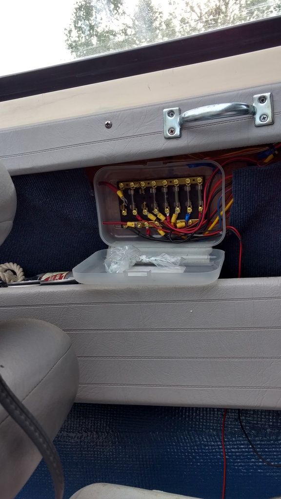
I have a 24v trolling motor that plugs in at the front of the boat, there are 4 cables running to the batteries but only 3 are hooked up and everything seems to be working fine with that..

Now the other battery has a million wires running off of it.

I'll attach a photo
 

Attachments

  • photo270177.jpg
    photo270177.jpg
    121.7 KB · Views: 0

winterhawk78

Seaman
Joined
Jun 20, 2017
Messages
51
you have at least 2
one is the motor that is its main power wires to the motor and to the controller and the functional part of the gages

second is all of the accessory, stereo,fish finder all of the lighting gage lights and so on

and third in your case is a 24 v trolling motor thats the tm and its own battery's, while it dosnt share the common battery's, its still separate

as you can see from the picture I posted above I have a mess. I would just like to figure out where all of it goes and if its not working fix it.
 

mxcobra

Chief Petty Officer
Joined
Jun 27, 2011
Messages
526
If it was me I would get out the volt meter , buy a busbar and ziptys and the rubber coated clamps,. and would start cleaning up things at the baterys. first. From there I would check volts at the switches (which are probably bad). then volts at the pumps you are having problems with if you get volts at the pumps then the pumps are bad. if all else fails I would run a ground loop around whole boat and new power wires to the accercery. from knowen good switches making sure a fuse was in line on each item like this and yes troilling motors do need a high amp circit breaker if it shorts with out one their could be a fire
 

gm280

Supreme Mariner
Joined
Jun 26, 2011
Messages
14,592
wh78, usually a wiring problem gets started like that when someone wires the boat and the wires are too long. They then just shove the extra wire to where ever it will go.

The proper way is to cut the wires to the proper length and wire tie them in a neat group branching off when each wire has to go. And I like labeling them as well so you never again wonder what each wire of for. But that takes some time and effort. But it eliminates confuse later on down the road as well. And one other thing you can do as well, and that is make a wiring diagram for you boat. A schematic diagram will stay with you boat and provide quick reference when looking to figure out a new addition or check on how everything is presently wired.

Those ideas are just how I like doing things. But others have their own ideas as well. JMHO
 

winterhawk78

Seaman
Joined
Jun 20, 2017
Messages
51
If it was me I would get out the volt meter , buy a busbar and ziptys and the rubber coated clamps,. and would start cleaning up things at the baterys. first. From there I would check volts at the switches (which are probably bad). then volts at the pumps you are having problems with if you get volts at the pumps then the pumps are bad. if all else fails I would run a ground loop around whole boat and new power wires to the accercery. from knowen good switches making sure a fuse was in line on each item like this and yes troilling motors do need a high amp circit breaker if it shorts with out one their could be a fire

thanks for the helpful tips
 

winterhawk78

Seaman
Joined
Jun 20, 2017
Messages
51
wh78, usually a wiring problem gets started like that when someone wires the boat and the wires are too long. They then just shove the extra wire to where ever it will go.

The proper way is to cut the wires to the proper length and wire tie them in a neat group branching off when each wire has to go. And I like labeling them as well so you never again wonder what each wire of for. But that takes some time and effort. But it eliminates confuse later on down the road as well. And one other thing you can do as well, and that is make a wiring diagram for you boat. A schematic diagram will stay with you boat and provide quick reference when looking to figure out a new addition or check on how everything is presently wired.

Those ideas are just how I like doing things. But others have their own ideas as well. JMHO

I diagram is a good idea, i'll make sure and keep one when I start rewiring
 
Top