You don't have "two" electrical systems on your boat. You actually have "three". 1) The engine electrical system is fed by the large battery cables that run from the battery to the engine. That system breaks down to several circuits that run up front to the controls, the instrument panel gauges and the engine ignition system and alarms. 2) At the battery there should be a smaller pair of #8 or #10 wires that again runs to the helm to power the switches and the circuits they control as well as other accessory circuits. 3) Your trolling motor batteries are a totally separate system and should not be tied into the engine electrical system.
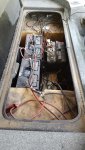
For the trolling motor, we need to know if it is a combination 12 AND 24 volt motor or 24 volt only. How is the boat currently wired for a troller? Is there a receptacle at the bow and how many terminals in that receptacle. There are a couple ways to do this and it involves either a two or four wire system. A two wire system as the positive of one battery connected to the negative terminal on the second battery. The remaining positive and negative terminals have wires that run to the receptacle at the bow. A four wire system has two wires running from each battery to a four terminal receptacle at the bow. A special four terminal plug with a jumper inside handles the 24 jumper that would normally be at the batteries in a two wire system. Yes, you need a circuit breaker in the positive lead. That should be a 50 - 60 amp breaker depending on the size of the trolling motor. If you use a four wire system, you need a breaker in both positive leads.
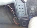
Wiring the helm (boat system) the main #8 or #10 feed from the battery feeds the INPUT to a fuse or circuit breaker panel. This lead needs a 20 or 30 amp breaker within a foot of the battery. Each circuit from the fuse panel is then fused according. You always want a fuse in any branch circuit and you do NOT fuse the negative lead. 16 gauge wire is adequate for nearly every branch circuit on the boat except for high power stereo systems or other high current draw items.
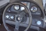
When wiring the gauges, each terminal on each gauge is jumpered from one gauge to the next in daisy chain fashion. For example the "I" terminal is the +12 volt feed on each gauge. The "I" terminal on the ignition switch provides that power to the first gauge in the string. You then jumper from that terminal to the next gauge and the next. Same for the ground and internal light. The "S" terminal is the sender terminal and those come from the fuel sender, trim sender and for the tach, from the engine harness.