Minn Kota 3hp...anyone have one?

jeepwm69

Petty Officer 3rd Class
Joined
May 26, 2010
Messages
84
Long story short, I have one I took apart, found the board was bad, and two years later someone is kind enough to rebuild the board.

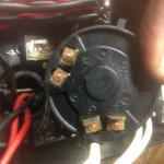
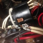
I've scrounged the parts, but have no idea how to wire the switch. I found this thread but the pic isn't very clear, and a lot of the wires are already off.

http://forum.tinboats.net/viewtopic.php?f=5&t=5453

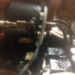
Anyone have one of these? Only 4 screws holding the top cover on. Would be very appreciative if someone would check a motor and give some instruction on what goes where.
 

gm280

Supreme Mariner
Joined
Jun 26, 2011
Messages
14,590
jeepwm69, If it is any help, the two white wires on each side of the controlling board are the same. Meaning the two wires on the left side are both the same, they are connected to the very same soldering pad on the board. Likewise the two wires on the right side of the board are the same and connected to their same soldering pad on the board. So you can install either one of those two wires from one side to where it goes without worrying about connecting it up wrong. Hope that helps a little. :noidea:
 

jeepwm69

Petty Officer 3rd Class
Joined
May 26, 2010
Messages
84
No Title

Thanks, that does help a bit.

The pic on tinboats shows two of the white wires off of one side that appear to be connected to each other (piggyback terminal on one of the white wires on each side of the board). The other looks different, at least in that tinboats pic.

I took good pics of all of this when I disassembled the motor, but once I figured out the board was fried, and found no replacements available, I deleted the pics.

What I have are
2 black and 2 red terminals coming up from the foot, which I have connected to the board (from the tinboats pic)
I have 4 white wires coming of of the board, and two of those have piggyback terminals on them.
I have 2 red and 2 black terminals coming from the battery cables as well.

I've pictured the switch. There are 4 terminals (marked) on the back of the switch, and two terminals on either side of the switch. The tinboats pic shows two of the white wires going to one side terminal, and then on the other side it looks like the white wires go to different spots.

I know a few of these motors are still floating around and am hoping someone will remove the 4 screws to the top cover and snap a pic so I can make sure I don't fry this nice newly rebuilt board.
 

Attachments

  • photo255927.jpg
    photo255927.jpg
    140.9 KB · Views: 1
  • photo255928.jpg
    photo255928.jpg
    211.2 KB · Views: 1
  • photo255929.jpg
    photo255929.jpg
    211.8 KB · Views: 1

jeepwm69

Petty Officer 3rd Class
Joined
May 26, 2010
Messages
84
Great news! Brenda at Minn Kota found me a diagram for the switch. I'll get things hooked back up this weekend and hopefully will have this one ready to be used again!
 

Attachments

  • 3HP SS TM.pdf
    116 KB · Views: 14

gm280

Supreme Mariner
Joined
Jun 26, 2011
Messages
14,590
Well that solves everything. Let us know how it works. :thumb:
 

sam am I

Commander
Joined
Jun 26, 2013
Messages
2,169
Love bringing old electronics back from the dead, esp. if you've had to replace fried components. Perhaps analogous to a engine rebuilder firing up and hearing the first breath of that motor roaring to life or a pilot lifting off the runway in a rebuilt plane for the first time but, only in a semiconductor nerdy sense ;) GM! Awesome job on that board man!!
 
Last edited:

jeepwm69

Petty Officer 3rd Class
Joined
May 26, 2010
Messages
84
Finally got to try this out last night and .....nothing.

Double checked wiring- correct

Jumped battery leads to wires going to bottom- prop kicks on

Only thing I can think of is maybe the switch is fried too.

I can verify the board is working properly by measuring the voltage output on those white wires coming off of the board correct?
 

jeepwm69

Petty Officer 3rd Class
Joined
May 26, 2010
Messages
84
I've possibly found a switch, but wanted to make sure that the switch is the problem, so I got after it with a voltmeter and probably not even enough knowledge to be dangerous. I've PM'd this info to gm280 because he seems to be a genius on this stuff, and has been so helpful thus far, but figured the answer might help someone in the future if I posted it on the regular board.

Motor runs fine if I take the red and black leads and connect them to 12V directly (red to +, black to -)

When hooked up as shown in the diagram Minn Kota sent me, I get nothing
.
Hooked a Voltmeter with neg probe to battery -, and then checked terminals on switch.

All 4 white wires coming off the board show 12V. These are what I would say are "power in", so that seems right.

There are two red wires and two black wires coming off the switch, so in my simplifying mind, these are "power out" and one red and one black would be forward, and the other red and black would be reverse. I could be way off on that.

When I turn the switch on, regardless of whether I click to forward or reverse, I get full 12.5 volts (what the battery shows) to ALL 4 of those connections, both red and black, so to me that says the switch is shorted. I would expect the red terminals to read 12 V, and the black terminals to read nothing when probed with the + probe from the voltmeter, and the - probe going to - on the battery.

On the speed controller does that disc lower the voltage or space out the "pulses" more for lower speeds?
 

sam am I

Commander
Joined
Jun 26, 2013
Messages
2,169
It varies how much the time the pulse is on, they'll go from off to full on or 0% to 100% duty defined by % Duty Cycle = (Ton/(Ton + Toff))*100.

My guess is the power FET's are wired as low side switches and are not being turned on (is why you see 12V everywhere). Low sides switches hard wire the high side (12V) and switch the low (ground) sides

Meaning, when the N-channel FET turns on via the controller, it'll ground the the motor's low side winding while the switch/relay's are holding the other side of the motors winding hard tied to 12V.

See Simplified Drawing Below.......


PWM TROLL.jpg


My bet is the PWM controller/oscillator is dead (or the path from, see R above)) and the FET's aren't able to turn on.......Is the PN's on these IC's?


A9R2B4A.jpg
 
Last edited:

jbcurt00

Moderator
Staff member
Joined
Oct 25, 2011
Messages
24,863
Add an @ infront of a users name and it'll notify them that you referenced them in a post

@gm280

jeepwm69
 

sam am I

Commander
Joined
Jun 26, 2013
Messages
2,169
Put another way Jeep the way the circuit works, it's like hard wiring the + side of the motor with a jumper wire to the battery's + side, then on the motor's - negative side, you've wired a toggle switch in series to the battery's negative post which allows you to turn the motor on or off.

Switch on (ton) = the motor runs. Switch off (toff) = the motor stops. Switch on and off rapidly varying the ton/(ton + toff)) = speed control (PWM)

If the motor is stopped, the switch is open obviously and if you probe the motor's wires, you'd see +12 on all the leads.
 
Last edited:

jeepwm69

Petty Officer 3rd Class
Joined
May 26, 2010
Messages
84
But what I'm getting is no voltage on the terminals that lead to the armature with the switch off, and 12V leading to the armature on both red and black wires (all 4 of them) with the switch on in either forward or reverse.

So what you're saying is the PWM pulses a ground connection, and there's constant 12V going in on the + side?

When wiring up lights I always have constant 12V to the light, and then ground the negative side with the switch. Same basic concept, right?
 

jeepwm69

Petty Officer 3rd Class
Joined
May 26, 2010
Messages
84
I think the way I'm checking for power might not be the right way to go about it in this setup.

How should I go about troubleshooting it? I've got a voltmeter. I have 12V going to the board. I have 12V coming out of the board and going into the switch. That's where it gets tricky.

If I pull the leads coming off of the switch (red and black) and connect them to 12V the motor spins, so I know the bottom end works.
 

sam am I

Commander
Joined
Jun 26, 2013
Messages
2,169
So what you're saying is the PWM pulses a ground connection, and there's constant 12V going in on the + side?

Typically yes, simpler designs such as this (no dc-dc up converters, i don't see one used here but, I don't have a schematic, so guessing a bit here based on pictures) use this method due to that the inherency of the FET transistors. The Ron(channel resistance when the transistor is turned on) of the N channel FET are much much lower as opposed to the P channel FETs which would typically be used as high side switches.

When wiring up lights I always have constant 12V to the light, and then ground the negative side with the switch. Same basic concept, right?
Yup
 
Last edited:

gm280

Supreme Mariner
Joined
Jun 26, 2011
Messages
14,590
Sam I am

@jeeppwm69,

The two DIP IC's you asked about were changed with two new ones. In fact every active component on that controller board has been replaces. The Power MOSFETS were basically toast when I got the board. And I actually remove at least one leg of every passive part and read their numbers as well. So everything was checked and verified good, or changed with new parts. One of those 8 pin DIPs was a standard Op Amp while the other was a PWM circuit. And since it was a high failure item, according to a lot of wed-site I searched, I just when ahead and replace them both. So other then wiring, I can't think of anything that is wrong with the controller board.

If there is any way to get the wiring schematic AND the controller board here at my house with the supporting switches and such, I could connect it up to one of my trolling motors and see what's up. At the time I had the controller circuit board here for repair, I had no idea how it was connected from the battery to the motor. But since that time, Minn Kota offered the schematic diagram and that would surely help. JMHO
 

sam am I

Commander
Joined
Jun 26, 2013
Messages
2,169
gm,

What was the part number on the PWM chip?...Thinking we could have jeep look for B+ with the board powered up on that particular pin at the least as a starting point. Could be a few things but wanted to look at the obvious first I reckon. If the PWM IC is powered up, maybe have him probe the Vout (waveform should have AC components)
 
Last edited:

gm280

Supreme Mariner
Joined
Jun 26, 2011
Messages
14,590
gm,

What was the part number on the PWM chip...thinking we could have jeep look for B+ on that particular pin at the least.....

Sam, the PWM chip was a Texas Instrument UC3842N, and the op amp was a typical LM358P. Pin 7 is the +VCC supply and pin 5 is the ground for the UC3842N. Pin 8 is +VCC on the LM358P Op Amp DIP and pin 4 is the ground. Hard to trouble-shoot things via comments. JMHO
 

sam am I

Commander
Joined
Jun 26, 2013
Messages
2,169
Thx gm,

Jeep, check pin 7 (Vcc) to pin 5 (Gnd), should be at least 12V. If you have power, check pin 6 to pin 5 for something other then 0V (modulating DC will have a AC value, so use AC scale on DMM).

Guessing pin 6 drives a/the FETs gates through a resistor of some low'ish value........Maybe an open gate resistor (see "R" above in simplified schematic above) since the FETs and this drive IC most likely smoked.......just a guess though.

Pin 4 should be wiggling too (RC oscillator), check with DMM on AC as well, should be something other than 0V.

20098811501788701.jpg
 
Last edited:

jeepwm69

Petty Officer 3rd Class
Joined
May 26, 2010
Messages
84
LOL. Thanks for the help guys. Sam I am, can you put that in more of a 3rd grade level, like "Put your voltmeter probes on this doohickey and that thingamajigie"?

I'm guessing the pins you are referring to are on the board?

Also please keep in mind that my voltmeter skills are pretty much limited to reading volts (I work on golf carts, ATVs, etc a lot).

I am willing to learn, I just don't want to short out anything poking around on this thing after gm280 went through the trouble to rebuild it.

If I can't do what needs to be done here, I'll drop the whole control board, switch etc in a box and send it back to gm280 (assuming he is still willing).
 
Top