Minn Kota ss 3hp motor desperate to find one

gabbysaslan

Recruit
Joined
Sep 8, 2016
Messages
4
My son sold an old motor from our garage that he thought was ours, but it actually belonged to a friend of ours whose husband died. I tried to find out who had the motor but the pawn shop is unwilling to give us the information of the buyer (ugh):mad:. So, now I am left with trying to replace it. I have searched everywhere I can think of, ebay, amazon, just googling it, but nothing for sale. This is the information I have on the motor: Minn Kota ss 3hp MK1086636. Does anyone on this forum know where I might find a working Minn Kota ss 3hp motor for sale? I feel horrible because this motor belonged to her late husband and Im sure has sentimental value :blue:. My email is bakelaurie@gmail.com if you have any information. Thanks Laurie.
 

gm280

Supreme Mariner
Joined
Jun 26, 2011
Messages
14,593
:welcome: gabbysaslan to iboats. glad you decided to join us here...

Before you go too much further, have you actually talked this over with the lady whose husband owned it? Maybe she really doesn't want it and you can offer her the money it was sold for. I can understand sentimental keepsakes, but usually not a trolling motor. So I would have a sincere heart to heart talk first before more searching. But that is just me. :noidea:
 

fishrdan

Admiral
Joined
Jan 25, 2008
Messages
6,989
Took me some searching to see exactly what that TM is, and it's an old one and going to be hard to find, probably from the 70's or 80's. Ebay is you're best bet to find one, and will be like finding a needle in a haystack. Not much value in that vintage of TM and most are probably broken or thrown away by now. You could also search google images, and click on the ones that look like the TM you're trying to find, might be for sale or sold already.

I like gm280's idea as the lady may want to have something other than an old crusty trolling motor. Maybe a bunch of yard work and/or house painting from the young man who sold the trolling motor.... LOL
 

gm280

Supreme Mariner
Joined
Jun 26, 2011
Messages
14,593
gabbysaslan, after thinking about this for a while, even if you did located another TM of the exact same vintage, it really wouldn't be the original TM and therefore she may not want it at all. I'd still try the talk first. JMHO
 

gabbysaslan

Recruit
Joined
Sep 8, 2016
Messages
4
Yes, it may come down to talking to her and coming clean about what my son did. She's not an easy person to talk to so that is why I really wanted to just replace it, but now that I realize how rare/old they are it doesn't sound like it's going to be easy. Maybe I can try again with the pawn shop but they would probably say the only way is to say it's stolen and file a police report, which I'm not going to do, although I feel upset enough with him to do it (why he thinks everything in the house belongs to him I don't know). He will be paying back the expense from his school money that is for sure. I have searched ebay and I did use google images and found a couple that looked similar (honestly I never looked that closely at it) but the trick seems to be the "ss" I don't know what that means but that seems to make it even harder to find. Can I call the company and give them that serial number and get an exact description or maybe an old manual with a picture on it?
 

gm280

Supreme Mariner
Joined
Jun 26, 2011
Messages
14,593
Yes, it may come down to talking to her and coming clean about what my son did. She's not an easy person to talk to so that is why I really wanted to just replace it, but now that I realize how rare/old they are it doesn't sound like it's going to be easy. Maybe I can try again with the pawn shop but they would probably say the only way is to say it's stolen and file a police report, which I'm not going to do, although I feel upset enough with him to do it (why he thinks everything in the house belongs to him I don't know). He will be paying back the expense from his school money that is for sure. I have searched ebay and I did use google images and found a couple that looked similar (honestly I never looked that closely at it) but the trick seems to be the "ss" I don't know what that means but that seems to make it even harder to find. Can I call the company and give them that serial number and get an exact description or maybe an old manual with a picture on it?

I do understand the hard to talk to type. I really don't have anything much to offer other then finding the person it was sold to, or posting a comment in the local paper about it. Either way, I don't see you coming out on the better side. But if you can't locate the original TM, what else can you do? :noidea:
 

gabbysaslan

Recruit
Joined
Sep 8, 2016
Messages
4
I'm going to the pawn shop today and otherwise I did find someone on craigslist selling a boat with the ss 3hp as part of the package. I asked if he would sell the TM separate but he doesn't really want to separate it from the boat. He said he would let me know if he is willing to sell. I guess I can keep scanning craigslist and ebay. Thanks for the advice I don't know how this is going to end but I'll try to find one until it's too late I guess :confused::scared:
 

gm280

Supreme Mariner
Joined
Jun 26, 2011
Messages
14,593
gabbysasian, do post the results either way. I'd like to know and I think others would as well. JMHO
 

jeepwm69

Petty Officer 3rd Class
Joined
May 26, 2010
Messages
84
Gabby, I got your PM over on the ATV board. I do still have my old S/S 3HP motor (either Saltwater Sealed or Stainless Steel depending on who you ask). It is not working, control board is burned up, and the top part of the motor is disassembled. The motor part does work if you apply 12V to the leads, but no way to control it as it is.

While I can appreciate your desire to "make it right" with the woman, I have to say that what you're talking about doing is giving someone a replacement something that you think has sentimental value. Do you think she'd want an old broken trolling motor that wasn't her husbands? Trying to pass off my motor or any other motor as her deceased husbands because it has sentimental value isn't honest. If you can't find the original, you should make your son go to her, tell her the truth, and either pay her for the motor or work it off. That's the right thing to do, not deceive the woman into thinking that some random old junk trolling motor is the one her late husband enjoyed for years.

My opinion of course, and you can do what you wish, but I would like to hold onto my old motor. I bought it new in the late 80's, and figure I'll be able to rig up some kind of speed controller to make it function if I ever get caught up on my other 1000 projects.
 

gm280

Supreme Mariner
Joined
Jun 26, 2011
Messages
14,593
Gabby, I got your PM over on the ATV board. I do still have my old S/S 3HP motor (either Saltwater Sealed or Stainless Steel depending on who you ask). It is not working, control board is burned up, and the top part of the motor is disassembled. The motor part does work if you apply 12V to the leads, but no way to control it as it is.

While I can appreciate your desire to "make it right" with the woman, I have to say that what you're talking about doing is giving someone a replacement something that you think has sentimental value. Do you think she'd want an old broken trolling motor that wasn't her husbands? Trying to pass off my motor or any other motor as her deceased husbands because it has sentimental value isn't honest. If you can't find the original, you should make your son go to her, tell her the truth, and either pay her for the motor or work it off. That's the right thing to do, not deceive the woman into thinking that some random old junk trolling motor is the one her late husband enjoyed for years.

My opinion of course, and you can do what you wish, but I would like to hold onto my old motor. I bought it new in the late 80's, and figure I'll be able to rig up some kind of speed controller to make it function if I ever get caught up on my other 1000 projects.

jeepwm69, I have been watching this thread and I too agree with your opinion. I basically stated the same thing previously as well. Oh thing that is interesting about your comment. You talk about the controller board being burned up. Is there any way you can post a picture of the top and bottom of the circuit board? I ask for multiple reasons. First I would like to see what they used for their controller. And secondly I may can tell which part or parts are suspect to repair it. Thanks either way, just wondering.
 

jeepwm69

Petty Officer 3rd Class
Joined
May 26, 2010
Messages
84
I'll have to dig the board up in the shop. One of the magnets in the bottom case broke and came unglued from the housing. I epoxied the magnet back together and bank into the housing, and now if I apply 12V to the + and - leads it comes on and works, but I get nothing when I have the board hooked up.

It had a black coating over the board on one side, but if I recall correctly I peeled part of it off trying to see if there was an obvious burnt connection I could attempt to resolder.

My father in law gave me a smaller, newer MinnKota so fixing this one went to the backburner.
 

gabbysaslan

Recruit
Joined
Sep 8, 2016
Messages
4
Hi jeepwm69, Thanks for getting back to me. I understand you want to hold onto yours and I'm sure you're correct that she would know it wasn't the original one.
 

jeepwm69

Petty Officer 3rd Class
Joined
May 26, 2010
Messages
84
jeepwm69, I have been watching this thread and I too agree with your opinion. I basically stated the same thing previously as well. Oh thing that is interesting about your comment. You talk about the controller board being burned up. Is there any way you can post a picture of the top and bottom of the circuit board? I ask for multiple reasons. First I would like to see what they used for their controller. And secondly I may can tell which part or parts are suspect to repair it. Thanks either way, just wondering.

Well it took awhile, but I finally found the board buried in ATV and Jeep parts in the shop. It has some kind of rubber coating that keeps one from really seeing the board itself. I can peel if off and take another pic if need be, as it's not doing me any good in its current form.
 

Attachments

  • board2.jpg
    board2.jpg
    154 KB · Views: 2
  • board.jpg
    board.jpg
    158.6 KB · Views: 2
  • board3.jpg
    board3.jpg
    149.3 KB · Views: 1
  • board4.jpg
    board4.jpg
    151.1 KB · Views: 1

gm280

Supreme Mariner
Joined
Jun 26, 2011
Messages
14,593
Well it took awhile, but I finally found the board buried in ATV and Jeep parts in the shop. It has some kind of rubber coating that keeps one from really seeing the board itself. I can peel if off and take another pic if need be, as it's not doing me any good in its current form.

Okay now I see what they did. Can't say for certain, but it does look repairable to me. More then likely one or more of the power transistors (probably MOSFETs) are probably gone. Those are the rectangular shaped tab looking parts side by side all attached in a role. The relays can easily be tested. I wish I could see it in person and see it I could repair it. But that would mean you would have to send it to me and I certainly can't guarantee anything. If you want to try that PM me and we can make other arrangements. JMHO
 

jeepwm69

Petty Officer 3rd Class
Joined
May 26, 2010
Messages
84
I'd be happy to ship it to you. If you can repair it, great. If not, I'm no worse off. Please PM me your shipping address and I'll drop it in the mail. Sent you a PM too.
 

gm280

Supreme Mariner
Joined
Jun 26, 2011
Messages
14,593
jeepwm69, I have received your trolling motor controller circuit board. And I have already removed all the rubbery coating and tested all the parts. You did have a few blown parts and I already have them on order. They should be in in a day or two. I also took pictures along the way to show you what I did. That circuit is a typical PWM (Pulse Width Modulation) controller circuit the feeds four power MOSFETS (
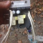
IRFP044NPBF) that were attached to the large heat-sink. The heart of the PWM circuit is a little eight pin DIP controller that is very prone to failure (UC3842N). So I ordered one of them as well. And that is because it would take more time to build up a testing circuit to test it then the two dollars for the replacement. The two power relays both had their coils opened. The contacts were in great shape.but without coils working they were useless. And that is odd because the driver circuits for them were not damaged. Two of the four power MOSFETS were toast. However since they cost a couple bucks, I am replacing all four with new ones. Here are some pictures;
001.JPG
Here is the board as I received it. The plastic round disk is actually a switching circuit to change the speeds.It uses tow flexible PC type plastic parts and when you pinch them together, it changes the resistance to change the drive circuit for the different speeds.
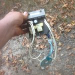
002.JPG
Just another angle.
003.JPG
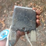
And the back side of the circuit board before I cleaned it off.
004.JPG
Here is the board cleaned of the rubbery coating. Yes that is a lot of rubbery coating there.
005.JPG
The cleaned board before I started testing. You can easily see the two relays and the four power MOSFETS on the heatsink.
006.JPG
Backside of the board after cleaning the rubber off.
008.JPG
Mounted and ready to test.
009.JPG
The power MOSFETS removed with the aluminum heatsink. The two filter capacitors tested good. They both read a little more then the actual value listed on the caps. But with such filter caps that is a good thing. So no need to replace them. All teh part that were attached to the heatsink were glued on. ANd teh screws were nearly impossible to break loose. In fact one screw for the dual Schottky diode pack broke trying to remove it. So I had to drill it out and retap the threads. All good now. All parts were tested for compliance and tolerance. All resistor were in their 5% tolerance ranges and no need for any replacement for them.
001.JPG
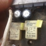
Here is the heatsink before cleaning it up. notice the parts in the background. Those are the bad parts. I opened up the relays to see what was wrong with them and the wires were either not connected, ot broke somewhere in the coil windings.
002.JPG
And the heatsink cleaned waiting for the new parts to get here.

Well that is about it until the new parts arrive. Since I don't have all the other pats of this trolling motor to actually test it, I figured if all the part are tested and known good, when you get it back it should work perfect. I don't see any issue with it working like new when you get it back. Just wanted you to see how it was coming along. JMHO
 

gm280

Supreme Mariner
Joined
Jun 26, 2011
Messages
14,593
Update, Late this afternoon all the electronic parts arrived. And tomorrow I should have this thing all built back up and ready to go. I am pretty sure this will work as good as new once it is installed back into the head housing. Every part has been tested and/or replaced. And unless there are other circuitry issues I don't have or know about, it will make the trolling motor sing and dance again. I'll post the finished pictures before shipping it back to you.
 

gm280

Supreme Mariner
Joined
Jun 26, 2011
Messages
14,593
Okay final update on this from my perspective on this trolling motor thread.

I soldered all the new components in place today and clean the entire board and even coated it with a few coats of Clear Lacquer to protect the circuitry. It is now totally finished and I will be sending it back to you so you can install it and have a working Trolling Motor again. For this rebuild, I bought all the new components through Mouser. They had everything at very reasonable prices and shipped pretty quickly as well. I will enclose the itemized list from Mouser for you to see.

Since I have no way to power it up because I don't have the trolling motor switches and actual motor unit setup, I can only assume it will work. And that assumption is because nearly every active component has been changed with new parts. The three transistors were removed and tested and did test good. And all the diodes and resistors and capacitors were tested as well. Every passive component tested in their percentage range and therefore they were not changed. Like previously stated, the caps tested to the high side. But being filter caps, that is not a problem in the least. All the resistors tested inside of their 5% tolerance range and remained on board as well. And all diodes tested prefect for a true diode capability. I have a few Fluke DVMs that have all those capabilities to test all such components.
001.JPG
As you can see the board is virtually stripped of all the components that I planned to change. And that includes even the dual op amp LM358 and the heart of the circuit the PWM chip UC3842. I could have made circuits to test them. But their cost were so little that it just didn't make any sense to do that.
002.JPG
And the bare back side of the board before I started soldering.
004.JPG
I started out building up the power MOSFETs and Dual Schottky diode heatsink assembly. All part have thermal grease or paste applied for heat dissipation. Something the original parts didn't have or it dried out years ago. And the Dual Schottky diode package also received a new insulator and hardware because it is not allowed to touch the heatsink like all the other components mounted to it.
005.JPG
Here is the board populated with all the new parts. Looks pretty good now. All the flux residue from soldering everything has been clean off with alcohol and an acid brush.
007.JPG
And a blurry shot with the 10 gauge wires soldered back on. Ready for clear coating now.
008.JPG
Areas taped off so they will be able to make electrical contact with the other parts of the trolling motor.
009.JPG
And the front side being coated.
010.JPG
And finally everything finished and ready to end. No there isn't any rubber coating because the coats of clear Lacquer does the exact same thing and allows more air around the board as well. It is moisture resistant, but not waterproof. In other words, it is not going to work if it is under water, but will work for the original intended purposes it was designed for.

Before and After TM Board.jpg

So that is the end of the rebuild of this trolling motor circuit board for "jeepwm69". You can see the before and after. I hope you likes it and enjoys your working trolling motor now.
 

sam am I

Commander
Joined
Jun 26, 2013
Messages
2,169
Looks good GM! You're hired man...........

What ya figure opened up those coils on the relay's? That's a weird one to have TWO relay coils open up, esp on a continuous op rated relay. Wondering if 24V/36V was somehow put across them and things snow balled from there.......

BTW, watch the ESD on those open circuited MOSFET's!! Esp on and around that carpeted area, that's flirting with......POOF!! I know, I know, everyone's is a critic but, that'll take'um out real fast!!
 
Last edited:

gm280

Supreme Mariner
Joined
Jun 26, 2011
Messages
14,593
Looks good GM! You're hired man...........

What ya figure opened up those coils on the relay's? That's a weird one to have TWO relay coils open up, esp on a continuous op rated relay. Wondering if 24V/36V was somehow put across them and things snow balled from there.......

BTW, watch the ESD on those open circuited MOSFET's!! Esp on and around that carpeted area, that's flirting with......POOF!! I know, I know, everyone's is a critic but, that'll take'um out real fast!!

Thanks for the heads up sam am i, I do know about ESD (my work days in repair), but the pictures were taken with everything sitting on a cloth on top of the bench. So carpet was nowhere near any electronic components. Yea I can see how the picture makes it look like a carpeted area.

On one of the repays, I can see the fine wire broken just short of the lead going out of the package (had to open them up). The other one a internal open inside the wrap. I thought it interesting that both were opened as well being how the driver circuit was good. IDK. VOO DOO Tronics?

Interesting enough, replacing the active components did not cost much at all. I know some of these PWM circuit boards can cost in the hundreds of dollars as replacement. But if you added up all the parts, it would even come to $45 dollars total or even less. I guess R&D kicks in.

I had a gut feeling the MOSFETS were going to be the problem even before seeing the board. And I was right as well. But that is usually what goes on a PWM circuit. The PWM driver chip could be good. But after researching that chip, it is a high failure rate part. And since it cost so little, I just decided to change it rather then built a circuit to test it. The datasheet explains how to test it with a circuit design. None of the parts were expensive at all. That was the good thing about it.

It was really fun to work on and find the defective parts again. I used to (decades ago) repair black boxes for military aircraft before going into Reverse Engineering, Circuit Design and Computer Programming.
 
Top