76 Evinrude 35 HP

MadThumper

Cadet
Joined
May 14, 2016
Messages
13
I just bought an evinrude 2cyl 35 hp outboard, to replace mine that over heated I had a tiller and the one I bought has electric start, I'll combine both to make a dual start unit, problem I'm having is trying to find a wiring diagram for the start/kill switch 12v charging , I have 5 wires coming from the motor which I dont know does what,, Does anyone have a diagram as to which wire does what? It'd be much appreciated

Thanks

<Mike
 

mjf55

Chief Petty Officer
Joined
Jun 17, 2014
Messages
462
I have found one for a 25 HP, but it had 6 wires. How about you post a picture of the connector, engine side. Also, can you trace where each wire goes to the engine, that would help finding or devising a plan.
 

gm280

Supreme Mariner
Joined
Jun 26, 2011
Messages
14,592
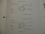
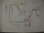
Here is two pictures from my 1976 40HP Johnson shop manual. They are not that clear so I hope you can read them.If not let me know and I'll try to get some better shots.
001.JPG
First one here shows both the engine side connector and the boat side connector that plug together. They are viewed looking at the pins and sockets.
002.JPG
This one shows the wiring at the engine side. Hope that helps a little. :noidea:
 

MadThumper

Cadet
Joined
May 14, 2016
Messages
13
MJF55, thanks, I had found that one too, too many wires and wrong colors. but thanks just the same

GM280, Yours seems much better, and the right colors, I had determined red and white to turn over the starter,, that leaves the other 3, Blue, B/W and P/W, I cant make out what the diagram says at the controls for those 3 colors,, could you just write down what they are meant for,, I assume one of them is the cut off for the motor, and I hope the other 2 are for 12 Volt supply for running lights and charging the battery,

I'm going to combine both motors together to have an electric start with pull start capability, adapting a start button on the tiller arm, I'd wish I could mount the For/Rev onto the tiller too, but I'm sure I'll figure something, lol

Again I thank you guys for your help.

Mike
 

gm280

Supreme Mariner
Joined
Jun 26, 2011
Messages
14,592
MJF55, thanks, I had found that one too, too many wires and wrong colors. but thanks just the same

GM280, Yours seems much better, and the right colors, I had determined red and white to turn over the starter,, that leaves the other 3, Blue, B/W and P/W, I cant make out what the diagram says at the controls for those 3 colors,, could you just write down what they are meant for,, I assume one of them is the cut off for the motor, and I hope the other 2 are for 12 Volt supply for running lights and charging the battery,

I'm going to combine both motors together to have an electric start with pull start capability, adapting a start button on the tiller arm, I'd wish I could mount the For/Rev onto the tiller too, but I'm sure I'll figure something, lol

Again I thank you guys for your help.

Mike

I?ll give it a try.
The Blue wire goes to one of the two spark coils on the primary side.

The Blue/White wire goes to the other spark coil as well on the primary side.

Those two wires go to the ignition switch and are shorted together to stop the engine when the key is in the "Off" position. One of the wires goes to the ignition switch and attaches to the terminal marked ?M?. The other wire also goes to the ignition switch and attaches to the other terminal marked ?M?.

The White wire goes to the starter solenoid (small terminal). It also attaches to the ignition switch terminal marked ?S?. If you have a neutral safety switch on your engine, then a white wire also goes to the neutral safety switch coming out from the other starter solenoid small terminal. So only when the engine is in neutral will there be a complete grounded circuit to allow the ignition key to crank the engine over.

The Purple wire goes to the choke. It also goes to the ignition switch and attaches to the terminal marked ?A?.

The Red/Purple wire comes from a fuse. The other end of that fuse is a Red wire that is attached to the starter solenoid that is also connected to the battery positive terminal. That Red/Purple wire also attaches to the ignition switch terminal marked ?Bat?.

The Large Red wire that attaches to the starter solenoid comes from the battery Positive terminal.

There is a Small Red wire that comes from the rectifier output that attaches to the same starter solenoid that the Large Red wire attaches to as well. That is how the battery gets charged.

And of course the Large Black wire comes from the Negative battery terminal and attaches to the engine block.

Hope that helps a little. :noidea:
 
Top