Alternator Upgrade on 1985 Mercruiser 260 (and 3rd Battery?)

Joined
Dec 17, 2013
Messages
20
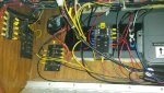
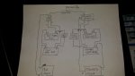
With all the electronics/lights/downriggers/wash down pumps/etc/etc my 1985 30'sundancer has, I experience frequently voltage drops when more than a few items are running at the same time... Current battery configuration is three batteries, one dedicated to the port motor, and two group 27's dedicated to the house/starboard motor. The starboard has a standard switch which I leave in "combine' mode at all times.

First and foremost, I am doing some re-con work by checking the battery condition via hydrometer, load tester, etc, along with having the current (NEW in 2014) alternator tested to ensure both pieces are functioning properly. Then due to the age of the boat, I am also going over the existing wiring to ensure there isn't any corrosion not only the connections but in/on the wiring itself.

So far, all checked out - so lets talk alternator upgrade - the 55AMP stocker isn't cutting it anymore (or so I think?), so I've found 75AMP options that are "bolt in". I am interested in cutting to the chase and getting a proper 100+ amp alternator - what are my options? I know the charge wire will need to be upgraded as the factory wire (8awg?) won't cut it.

Also, since I am into overdoing it at times, I have thought about adding a 3rd group 27 deep cycle to the starboard to mitigate any drops under load - overkill? Stick with alternator upgrade ? Or scrap alternator upgrade and just add this third battery?

Looking for thoughts/ideas.
 

bruceb58

Supreme Mariner
Joined
Mar 5, 2006
Messages
30,478
What kind of voltage drops are you getting? Have you measured the drops at the battery and at the load to make sure it isn't your existing cabling?
 
Joined
Dec 17, 2013
Messages
20
The starboard (house) volt meter runs around 14-14.2 volts with engine running (like normal) - turn ANYTHING on and it begins to drop, the more "things" I turn on, the more the voltage drops (lights dim as meter drops too, so it's not a guage issue). Flush the toilet (run macerator) and good bye radio (turns off) if on.

Checked So Far:

Both batteries used on the house/starboard start were low on water in the cells. I filled both batteries to the bottom of the sight holes as directed with new distilled water, charged, and only one came back with good readings on all cells with hydrometer. The other battery has a bad cell still - that battery is being replaced.

My cable check is only visual - no major corrosion found (just minor surface that accumulates after a tough season or two) I want to cross as much off the list during the off season by checking/replacing lugs if/as needed. I didn't see evidence of the original cabling being in poor repair when checked. (2 AWG wiring) I am going to cut each cable 2-4" shorter to reveal the inside condition, and replace with new tin plated lugs (Yes i have the proper lug crimpers!)

I guess my question is the 3 battery approach for house and starboard starting batteries overboard? I plan to keep the port isolated to two group 24's (I actually have the second port battery running a few randomly used accessories to help "lighten the load" - the port never shows signs of voltage drop - no issues whatsoever.

I plan to check the alternator tomorrow to rule that issue out - but if it's good shape, i'd love to toss in an upgraded one just to ensure i can turn on all the things without worry - again, I like to do things "RIGHT" and ensure I NEVER have this issue again - it sucks!!!

Thanks for the input!
 
Last edited:

bruceb58

Supreme Mariner
Joined
Mar 5, 2006
Messages
30,478
If you can separate the house that is fine. Personally, I don't see why you need two batteries in parallel as you have it now. Make them separate. Have all the house stuff on one battery and get an ACR(Automatic charge relay) to charge it. I never leave a battery switch in combine mode. If one battery has a bad cell, it will drop the good battery voltage down and damage it since you can never fully charge it.

If you want a higher capacity house, buy 2 Trojan 6V golf cart batteries and use them as a house bank.

Out of curiosity, when you are done for the day, what do your batteries measure at? That will really tell you if you alternator is sufficient or not. No problem in adding a 100A alternator but I kinda doubt the alternator is your issue.

Where is your Voltmeter measuring the voltage? Likely, it is at the helm which makes sense that you have a voltage drop between your battery and the helm where your accessories are likely attached. Your alternator has nothing to do with this. Measure the voltage at the battery with a handheld meter when you turn things on and it will likely show very little drop.
 
Last edited:

fishrdan

Admiral
Joined
Jan 25, 2008
Messages
6,989
If wiring is causing the problem, adding batteries or upgrading the alt won't help.

I'm with Bruce, check for voltage drop, verify the wiring is in good condition, and connections clean and tight. Closely inspect the grounds, especially the battery cable->engine ground lug. Where are the grounds for the high amperage accessories terminating and what types of loads are you pulling from the battery(s) when you see voltage drop, how many amps? Also, is the engine running when you see the voltage drop, or is the engine off?

A 105 amp alternator will put out 105+ amps at high RPM, or around 60 amps at idle. That's a lot of current going into discharged batteries, but if the battery isn't discharged it will certainly keep up with your loads. I have one on my 3.0L engine and charge discharged trolling motor batteries while trolling off the main engine. Even at idle I think it's borderline overcharging - charging the batteries too quickly. I don't like charging the discharged batteries at high RPM as it hits the batteries too much current, and the alt gets really hot, stinks to high heaven. (The spark proofing screens in the alt cut cooling efficiency......)

On my engine the stock alt wire was 10ga (same for yours?), which is fine for the short wire run coming off a stock alternator. You are right that the alt + wire should be upgraded if going to a high current alt, I used some 8ga wire I had left over.

EDIT: I didn't see your post update, that voltage drops with the engine running. I would definitely troubleshoot the wiring and check voltage drop before adding another battery or upgrading the alternator.
 
Last edited:
Joined
Dec 17, 2013
Messages
20
No Title

Update:

Alternator checked out great - no issues there.

So i crawled back in the boat and checked the terminal ends on the battery cables to find a decent amount of corrosion there. Also, each of the starters has two, 2 AWG wires coming off them, so i traced those and one of the wires essentially connects both starters together, with this piece that appears to be a relay of some sort (probably the "emergency start"??)

If indeed the emergency start, i would look to remove this all together, and delete this cabling as I will be running two batters, with two switches already...unless there is a compelling reason to keep this?

Lastly, what the hell else is connected to this starter? I believe the orange wire comes from the alternator, one of the large red 2awgs goes to the battery, the other to the aforementioned relay looking thing then ultimately the port starter, the red wire goes to the power trim/tilt unit I believe, but about that flappy red jacketed wire? Looks to go to the engine harness - is that the house power supply? It must be as I can't seem to find where the house power comes from...

Next step, new batteries and checking the wiring condition....
 

Attachments

  • photo237003.jpg
    photo237003.jpg
    133.5 KB · Views: 0
  • photo237004.jpg
    photo237004.jpg
    149.5 KB · Views: 0
Last edited:

fishrdan

Admiral
Joined
Jan 25, 2008
Messages
6,989
Those cable ends don't look in that great of shape, but, if the engine is cranking over fast and not dragging, the corroded battery cables are not your problem. It takes far more current to crank the engine than operate downriggers and those other accessories. That said, I would fix the corroded cable ends and replace them with tinned lugs, possibly change the cable if it's corroded too. Bare minimum, remove and clean the cable ends, then reinstall.

The starter pic is kind of obscured, but the wires look OK. Not sure what the sheathed on is for, alt or engine harness would be my guess. I would leave the solenoid, just in case the port battery goes dead, though I think you said you were dual battery-ing each engine, so the solenoid may be moot.

For the voltage drop, I would trace back from the high current accessories and find out what their power path is, to see what's causing the voltage drop. If all of those accessories are using the engine's wiring harness to draw power, that very well could be your problem as the stock harness (wires in the cannon plug) are not designed for heavy loads like you mention. The cannon plug pins/sockets could also be corroded, and need cleaning. I would think those loads should be pulled off a separate fuse/breaker panel, with separate + and - wires going back to the house batteries. You will need heavy wire/cable powering this fuse panel, 10 -> 8 ga wire would be my guess, but this would be dependent on the current draw and how long the wire runs are. You can use "blue seas dc wire calculator" (google it) to see what size of wire is needed. (I have a 24V trolling motor that can draw 42 amps, and needed to use 6ga wire due to the cable lengths, and to avoid excessive voltage drop.)

If you need wiring, genuinedealz.com sells tinned marine cable, wire and lugs inexpensively, only takes 2-3 days to arrive.
 
Last edited:
Joined
Dec 17, 2013
Messages
20
Anyone happen to have what cables coming out of the engine harness, going forward are for? Like orange = volt guage, etc? Otherwise I'll keep searching, im probably just using the wrong search words.

Thanks for the advice!
 

Bondo

Moderator
Staff member
Joined
Apr 17, 2002
Messages
70,524
Anyone happen to have what cables coming out of the engine harness, going forward are for? Like orange = volt guage, etc? Otherwise I'll keep searching, im probably just using the wrong search words.

Ayuh,.... Welcome Aboard,.... In my signature is a link to Don'S Adults Only section,...

In there are links to the factory Merc manuals, which all have wirin' diagrams,...
 

bruceb58

Supreme Mariner
Joined
Mar 5, 2006
Messages
30,478
Your voltage is being measured after your ignition switch.

This is what you need to do to measure voltage drop.

1) Get some long test leads
2) Turn on all your loads
3) measure the voltage with a handheld meter between the positive post of your battery and your helm fuse box positive bus.
4) repeat for negative side. Negative post and negative bus at fuse block.


This will tell you what side has the voltage drop that is affecting you the most. Will be a voltage less than 1V likely. Report here what you find. Once you know that, you can start measuring voltage drops at intermediate points.

In addition, measure the voltage at your battery with all your loads on.
 

Scott Danforth

Grumpy Vintage Moderator still playing with boats
Staff member
Joined
Jul 23, 2011
Messages
47,538
That green looking battery cable would have me changing the cable
 
Joined
Dec 17, 2013
Messages
20
Well i'm officially stumped on where the hell the house power comes from - The only connections I have at the batteries are the 2 AWG leads from the starter motors. No wire for house on the batteries, nor starter posts.. Boat is a 1985 sea ray sundancer, with twin 260's and alpha drives.

I see the factory power distribution (with old school fuses) under the dash, and the red 10awg looking power supply wires to both factory fuse blocks, but cannot locate those same wires in the engine compartment for the life of me. They have to be grabbing power somewhere, but im probably too dumb to find where - any suggestions on other locations? Not on the batteries themselves, nor starter posts.
 
Last edited:

bruceb58

Supreme Mariner
Joined
Mar 5, 2006
Messages
30,478
My bet it is coming from the starter post. Those red 10AWG wire is likely going back to the starter posts. Just take one of those cables off at a time and see when you lose voltage at the fuse panel.

On some boats, its very difficult to make a separate house circuit since that fuse panel also supplies your ignition and you don't want that to be on a house circuit. You almost have to have two sets of fuse panels. One for house and one for engine.
 
Last edited:

Scott Danforth

Grumpy Vintage Moderator still playing with boats
Staff member
Joined
Jul 23, 2011
Messages
47,538
Most likely coming back thru the wire harness to the key switch.

I added 4 gauge wire runs for a dedicated house load panel. Courtesy lighting, electronics, audio, and power outlets are connected to a separate terminal strip and 100 amp breaker Are fed off the house battery. Gauges, tilt/trim, motor, and nav lights on the primary battery
 
Joined
Dec 17, 2013
Messages
20
No Title

Well I had successful day on the boat - pulled off the two wires (one to battery, one to "emergency start") from the starter posts and they looked like hell. One of them was corroded half way through. The good news is after cutting each cable two inches down, the copper looked fresh! Then I cut another inch off just to be sure, sure enough, copper looks brand new. So I can indeed salvage these wires, new tin plated terminals are on order!

Also, after tracing the power wires and getting my hands on a mercruiser shop manual (volume 9 i believe) it looks like the "house" power is run off the engine harness in my boat..The wire looks to be 10 awg? (Red/Purple stripe). Nothing else came off the starter besides the two, 2awg aforementioned wires, 1 orange alternator wire, and 1 red/purple wire (goes to engine harness, then to dash). So the solution there is Scott's (great idea! Thanks Scott!) - and that's to run my own 4 AWG wire up to my existing blue seas fuse block, then run a pigtail 4 awg power supply/ground to a second blue seas fuse block to replace the remaining two old glass tube fuse panels. Then, I will see what the dual buss is on the far left (no fuses in photo) - and see what that feeds (guessing power in from engines, then split to factory panels..I hope!).

Either way, three faults have been identified:

1) One Battery with a dead cell - Solution: Replace with New Group 27 Deep Cycle for House
2) Corroded Terminal Ends on Both Starters - Solution: Cut wire down 2-4" to fresh copper + Add New Tinned Terminals + Seal with adhesive shrink tubing
3) House appears to be supplied by engine harnesses on both engines (total of two 10awg wires to fuse panels): Solution: Run my own dedicated 4 awg to twin blue seas fuse panels - move existing wiring over to updated fuse boxes.

Photos attached for reference...

Also, I deleted the factory emergency start as both engines will have 2-3 batteries each with switches (and ACRs?)...This also freed up 2 awg wire formerly used as emergency link between two engines which now can be used in the rest of the custom cabling I will need to do! Just saved 50-150 bucks or so of cabling there to put towards switches/ACR. Boom!

The last question I have, is I would like to run 3 batteries off my starboard (main of the two engines - currently powers house). One to serve as primary starting battery, and two to serve as house batteries. Ideally the starboard alternator would charge all three while underway - anyone have a simple wiring diagram for that? Blue Seas has a similar one, but it doesn't accomplish charge all three while underway. Or would it be "better" to just run two group 27s off the starboard, one for starting, and one for house? (utilize Blue seas add a battery kit with ACR)....Or what about each engine uses a group 24 starting battery, and each has a deep cycle group 27 as house and use those two Group 27s together to power house?

Thanks all!

Robert
 

Attachments

  • photo237117.jpg
    photo237117.jpg
    140 KB · Views: 2
  • photo237118.jpg
    photo237118.jpg
    134.2 KB · Views: 2
  • photo237119.jpg
    photo237119.jpg
    219.7 KB · Views: 2
Joined
Dec 17, 2013
Messages
20
No Title

Thoughts on this schematic for the new way of wiring the batteries? Or Overkill on the house side?

Notes: I will be using two of the blue sea mini add a battery kit's (switch + ACR in each kit). Then the house load from each switch will combine on a blue sea bussbar (w/cover!), from that buss bar, a 4awg wire going to fuse panels under dash.
 

Attachments

  • photo237178.jpg
    photo237178.jpg
    137.9 KB · Views: 0
Last edited:

Bondo

Moderator
Staff member
Joined
Apr 17, 2002
Messages
70,524
I deleted the factory emergency start as both engines

Ayuh,.... Yer boat is 30 years old, that ain't a "Factory" wire/ cable,....
More like a backdoor/ pizz poor battery combiner cable,...

Then, I will see what the dual buss is on the far left (no fuses in photo) - and see what that feeds (guessing power in from engines, then split to factory panels..I hope!).

I believe those are the Ground circuit, buss bars,....
This is a Boat, ya gotta run Ground wires, no chassis to ground through,....
 

bruceb58

Supreme Mariner
Joined
Mar 5, 2006
Messages
30,478
If would not go with the mini kit. The normal kit has much larger switches and ACRs that handle more current. I use a mini on my pontoon boat but use the bigger one for my Wellcraft.
 

bruceb58

Supreme Mariner
Joined
Mar 5, 2006
Messages
30,478
The only question I would have is how the 2 house batteries connect. With both switches on, both house batteries will be connected together and both alternators will therefor be connected together. That may be fine but that is just a warning. You could have a switch up at your house bus to switch between which house battery you are running from.
 
Top