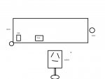
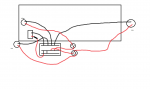
First, you have a specialty switch intended for nav light switching. However, you have given us no terminal labels on said switch so you need to search that out (unless someone comes up with which is +12V, stern and anchor terminals). You need to wrap your head around the fact that in one position, only the STERN light shall be on. The other position lights both the stern and bow lights. IN is the OFF position. This switch is designed so a diode is not required like a standard three position (three terminal) switch. If you know how to use an ohm meter, determining which terminal is which is rather simple. In the OFF position, one terminal will have no continuity between either of the other two terminals. That terminal will have +12 volts on it. Since you appear to use an old-style glass fuse panel, you run a #10 gauge wire from the POS terminal of the battery to a 20 amp fuse or breaker within one foot of the battery. From there, the +12 volt line would run to to the lower bus on your fuse panel. Insert a 7 amp fuse into one of the positions on the fuse panel and from the middle row terminal, run a 16 gauge wire to the switch. You also need a #10 gauge wire from the NEG terminal of the battery to the UPPER row ground bus. The ground lead (16 gauge) from both lights connects to any of the ground bus terminals. The POSITIVE wires (16 gauge) connect to the remaining two terminals on the switch. The other switches posted in this thread do not apply to you. They are standard switches and require entirely different wiring.