SportJet 90 PWC transplant

ondarvr

Supreme Mariner
Joined
Apr 6, 2005
Messages
11,527
You are confused as to how it works. The first amount of increase in RPM's and power is mostly from spark advance, then at high end the throttle opens up completely. If the timing and spark are out of sync you can burn holes in pistons, seize, coke up the rings, over heat, etc, resulting total destruction of the motor, and other unpleasant this like that.
 

ondarvr

Supreme Mariner
Joined
Apr 6, 2005
Messages
11,527
You are confused as to how it works. The first amount of increase in RPM's and power is mostly from spark advance, then at high end the throttle opens up completely. If the timing and spark are out of sync you can burn holes in pistons, seize, coke up the rings, over heat, etc, resulting in the total destruction of the motor, and other unpleasant things like that.

The link and sync (coordinating the movement of timing and throttle) is a critical adjustment for the engine to run correctly, you can'’t just wing it with two separate controls operated independently
 

WCTori

Seaman
Joined
Feb 21, 2015
Messages
53
Okay, thanks for that explanation of how the power comes on. If that's the case then maybe i'll be okay. I'll keep it this way and see how it goes. I'll start doing more research on twist grips that might offer more pull or leverage.

I appreciate your insight on this.
 

sjbs

Seaman
Joined
Dec 22, 2011
Messages
69
I have a Wetbike and know it is a tight fit for the 2 cylinder engine and you have 3.Are you using the Sportjet pump? Can you show more pictures? Thanks,Steve.
 

WCTori

Seaman
Joined
Feb 21, 2015
Messages
53
No Title

Here is a little update on this project and another plea for help.... ;)

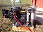
So the transplant is complete. I had to have a custom rear ski made to fit the Sport Jet pump, and have now fitted it all together. Lake tested last weekend with mostly positive results. The throttle is heavy, but works. It responds, and feels just like the outboard engine that it is. Slow to rev, slow to return to idle, and really starts to scream once the throttle plates are opened up. It's really quite odd how it feels like your running an outboard boat, and not a Wetbike. Anyway, she rips along nicely and i saw a max of 46.5 on GPS. This is about a 8mph bump over a standard Wetbike. I'm having trouble keeping the pump fed with water at higher speed/rpm, but have narrowed the rear ski 3" which will eliminate some of the lift, and should keep it in the water more. It was easy to get it to cavitate and hit the rev limiter, and if this mod to the ski doesn't do the trick, then i'll build an intake scoop to keep the jet pump fed better.

Also, this thing sounds amazing ! Wicked would be a good description. ;)

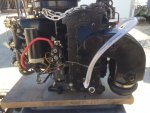
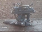
The biggest problem, and this is where i could use some input, is that the engine takes on water thru the exhaust. I expected this to be a problem since the engine sits much lower when stationary than it did when it was in the Jazz boat. (now its below the water line) So, i need to come up with a air trap in the exhaust to eliminate this. The original Wetbike engine has a pair of exhaust tubes that create a " P Trap " to keep this from happening. The exhaust layout on the Force engine is a bit different. I am going to try to find another exhaust manifold for the 90 Force engine that i can modify, that way if this doesn't work out, i can still put my boat back together. Here are a couple pictures of what i'm up against, and how the Wetbike engine solves the problem. Any input would be appreciated.
 

Attachments

  • photo233271.JPG
    photo233271.JPG
    126.3 KB · Views: 0
  • photo233272.jpg
    photo233272.jpg
    20.5 KB · Views: 0
Last edited:

pnwboat

Rear Admiral
Joined
Oct 8, 2007
Messages
4,251
Looks like you almost have to cut the exhaust outlet tube on the Force motor off and rotate it 180? and weld it back on so that it's pointing up instead of down? That way you can route the exhaust outlet so that it's up higher than the water level? I don't know if that's possible.
 

WCTori

Seaman
Joined
Feb 21, 2015
Messages
53
haha ! I'd have kissed you if you weren't 24 hours too late. ;) Discovered this was also called an L drive motor combo over the weekend. Searched ebay for "Force L drive" and came up with pages of dirt cheap parts. Also found that exh. elbow that you linked that will help me in my rework. Ended up getting a manifold for $40 + shipping, and an elbow for $9 + shipping. (also bought a 2nd elbow that came with a rubber coupler for $38) Luckily, i decided to wait on the parts motor i found 3 hours away for $400 that i ALMOST went down an bought yesterday. These cheap parts to experiment with have given me some excitement in the project.
We go again to the lake this coming weekend, and i'll be testing the 3" narrower rear ski that should help feed the jet pump better.

Thanks though PNWBOAT. I appreciate your recon.

I'm trying now to gain more knowledge on the other half of the L drive set up. I'm envisioning the L drive mounted to my rear ski instead of the jet pump. Would be much more efficient.
 

pnwboat

Rear Admiral
Joined
Oct 8, 2007
Messages
4,251
Yeah the Force "L" drive was an ill fated experiment that only lasted a few years. The outboard power head was mounted to the hull and connected to a separate outboard lower unit with a drive shaft with a U-Joint set up. Too many parts between the power head and lower unit. It was not reliable, parts were very expensive and hard to get.
 

WCTori

Seaman
Joined
Feb 21, 2015
Messages
53
That's what i'm learning. Lots of negativity regarding it, but no real accounts of what commonly fails. I'm trying to learn more about the set up, scouring Craigslist to find a boat for sale that i could go inspect. Maybe even buy if the price was right. Don't know if the set up would work for me or not, so i gotta get a look at one. Been looking at a lot of pictures on the net, but cant seem to figure out what's between the powerhead, and the lower unit. (If anything) I've seen the driveline, but can't figure out where it goes in the mix. Have any input ?
 

pnwboat

Rear Admiral
Joined
Oct 8, 2007
Messages
4,251
Basically they took a complete Force outboard and split the lower unit away from the power head, So the water line and exhaust run between the two via hoses.

Here is a picture of the power head in the engine compartment.

L drive.jpg


Here is the lower unit. Note the exhaust hose hanging loose and drive shaft w/u-joint. The drive shaft is inserted into the splined hole in the crankshaft. It had a weird number of splines. 13 if I remember correctly. No wonder it didn't do well.......13??!! If it had 14 or 15 it probably would have done better......on second thought...naw it was just a bad design LOL!

L drive lower.jpg

Here is what it looks like looking at a rig with the L drive set up.

L drive 1.jpg
 

WCTori

Seaman
Joined
Feb 21, 2015
Messages
53
Thank you again. This sentence " The drive shaft is inserted into the splined hole in the crankshaft. " is what i needed. That answers my question. I wasn't sure if there was something in between the lower unit and the power head. Okay..... have any experience with one ? The only think i've read where someone actually stated what failed was the rubber exhaust couplers. I'm not afraid of those, nor really any of the rest of it. After all this would not be typically used for hours on end like it would in a boat. More of a novelty build, used 20 minutes at a time, and might see 2 hours a year..... AND that's IF it was a successful endeavor.
 

WCTori

Seaman
Joined
Feb 21, 2015
Messages
53
No Title

So here is the missing mid section piece. Found this on ebay. This is what i was wondering about.
 

Attachments

  • photo233595.jpg
    photo233595.jpg
    204.7 KB · Views: 0

pnwboat

Rear Admiral
Joined
Oct 8, 2007
Messages
4,251
That is the piece that the power head sits on in the hull. The upper triangular part sits in the hull, the rest of it sits outside the hull and the lower unit bolts to it.

It's trianular shaped and you can see it in the first photo that I posted. You can also see the "arm" which is on top. That connects to the steering cable and turns the whole assembly for steering. You can also see the arm in the first photo I posted, and laying disconnected next to it is the end of the steering cable.
 
Top