1976 Tom Boy Boat, 1976 40 HP Johnson Outboard and who knows what Trailer

Woodonglass

Supreme Mariner
Joined
Dec 29, 2009
Messages
25,924
I'm gunna recommend that you post this on the general forum, the chat forum and then technical forum. I'm sure a LOT of people could benefit from your knowledge of circuitry!!!
 

gm280

Supreme Mariner
Joined
Jun 26, 2011
Messages
14,591
I'm gunna recommend that you post this on the general forum, the chat forum and then technical forum. I'm sure a LOT of people could benefit from your knowledge of circuitry!!!

Thanks WOG, but unless it is something the average guy can easily do or make, I don't see it being of much use. I mean I'm pretty sure there are factory sensor that do basically the same thing. And I would most certainly use a sensor like this then a float switch. I am sure if you would search for a no moving part water sensor, somebody has them. The fact that some have questioned the complexity, and I can honestly understand that as well, it leaves me to believe it isn't something most of the boaters are going to try and make... But that is just my opinion.

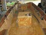
I guess I can post a few pictures of my latest progress on the boat. I have mocked up the rod boxes and I think they are going to work out nicely. I am using 1/4 (actually true 1/4" too) plywood for them. I figured once they are water proofed on both sides, they will be stout enough to do the job. And with well place little bulkheads, and mix and pour foam, I thing they will certainly be solid as well...
Rod Boxes (1).JPG
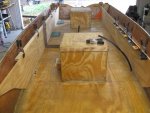
I am using a lot of clamps to keep the wood as straight as possible to get a good idea how they will look. And I am certain most anybody that has ever built anything for a boat, knows there are no straight lines and you have to contour the wood to fit the sides...
Rod Boxes (2).JPG
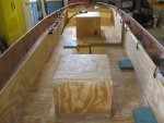
You can see the angled cuts on the front of the side wood. That is because of the sides are stepped and splayed outward as a lot of hulls usually are.
Rod Boxes (3).JPG
And a rear shot of them. I have to say, I've shopped or actually really just looked around at the usual stick steering type boats available around my area, and it looks like I have a lot more leg room in this boat setup then the usual stick steering boat. And we won't even get into the cost for such a new boat either. I figured I will have a very good bargain with this when finished...unless you factor in labor costs... :facepalm:

Once I get these finished and permanently installed, it is time to flip the hull and start prepping for paint... :whoo:

Until next time, you all have a magnificent day... :thumb:
 

gm280

Supreme Mariner
Joined
Jun 26, 2011
Messages
14,591
I presently have a brand new Moeller 6 gal plastic gas tank. And while it is new, I am not so sure I like its design. Does anybody have the dimensions for the older typical 6 gal metal tanks that the Evinrudes and Johnsons use to use? I 'd like to know that actual footprint of those older metal tanks to see if it would fit in the area I have reserved for the gas tank in my boat project. I see a lot of them are on EBay and was looking at them. But not one stated the dimensions of the tanks. Anybody have any ideas?
 

64osby

Admiral
Joined
Jul 28, 2009
Messages
6,799
Great job on the float sensor.

Would work great in a glass boat but copper isn't too friendly with tin hulls.

Do you think aluminum tubing would work for that application?
 

gm280

Supreme Mariner
Joined
Jun 26, 2011
Messages
14,591
Great job on the float sensor.

Would work great in a glass boat but copper isn't too friendly with tin hulls.

Do you think aluminum tubing would work for that application?

Aluminum will work and so will PVC pipe IF you like. You just have to install two wire probes inside the tube. Everything else stays the same with PVC but you can use two probes (wires) for the water sensors. On my first hull I installed this circuit. I took standard house wire and stripped back about an inch of insulation from each wire and stuck it at the height I wanted the pump to turn on. I like the tube or pipe for two reasons. First you can keep all the debris from contacting the sensors and keeping the pump running until the debris dries out, and secondly it keeps the pump from turning off and on from water sloshing around. But as I said my first hull setup was open to the world and I have zero issues with either of those things...
 

TruckDrivingFool

Lieutenant Commander
Joined
Jul 30, 2007
Messages
1,818
I'm with Woody that float sensor needs shared. :nod:

I'm barely an amateur hobbyist at electronics and I'd say it's simple enough that any fool (points finger to self) with a soldering iron could knock that out in no time. Even if it was just following the schematic and putting it together on some protoboard. (what I may do)

To show my gratitude I ran out and measured one of the old metal tanks - roughly 11.5W x 18.25L x 11.5-12H including the handle. Had to eyeball the height to the tape measure so YMMV
 

sphelps

Supreme Mariner
Joined
Nov 16, 2011
Messages
11,432
The water sensor switch you designed is probably easy for a lot of the guys here but unfortunately I'm not the sharpest tool in the shed when it comes to anything electronic .. :facepalm: Given time and guidance I'm sure I could figure it out but maybe not before the boat sank .. :lol:
Ok lets talk about the rod boxes ... I like what you have planed so far . How are you finishing the tops ? Hinged lids ? Thinking I may do something similar ...
 

Woodonglass

Supreme Mariner
Joined
Dec 29, 2009
Messages
25,924
I presently have a brand new Moeller 6 gal plastic gas tank. And while it is new, I am not so sure I like its design. Does anybody have the dimensions for the older typical 6 gal metal tanks that the Evinrudes and Johnsons use to use? I 'd like to know that actual footprint of those older metal tanks to see if it would fit in the area I have reserved for the gas tank in my boat project. I see a lot of them are on EBay and was looking at them. But not one stated the dimensions of the tanks. Anybody have any ideas?
I got two of em And I'll measure em tomorrow and take pics so you'll have the measurements.
 

gm280

Supreme Mariner
Joined
Jun 26, 2011
Messages
14,591
I'm with Woody that float sensor needs shared. :nod:

I'm barely an amateur hobbyist at electronics and I'd say it's simple enough that any fool (points finger to self) with a soldering iron could knock that out in no time. Even if it was just following the schematic and putting it together on some protoboard. (what I may do)

To show my gratitude I ran out and measured one of the old metal tanks - roughly 11.5W x 18.25L x 11.5-12H including the handle. Had to eyeball the height to the tape measure so YMMV

Well TruckDrivingFool, I hope you can build one and use it. It is a really simple layout and there is basically nothing peculiar with the parts either. I always try to design around off-the-self easy to procure parts. That way the cost is minuscule and ready available. And as compact as it is, it takes up so little space that any circuit board or even the that matrix board could be used... Thanks for the measurements of your tank as well. I will see if that will work better in the area...

Sam, I am still in the design phase of the rod boxes. But it looks like the bowed out sides offer me rod boxes without taking much if any floor space away. And since I will only use the top half portions, the bottom will also be filled with mix and pour foam below the floor I will install in the box sections. Parts of the top will be hinged with SS piano type hinges. But there will also be parts of the top that are not hinged as well. But I also have four cup holders to install in those sections for the driver and passenger areas. So when I finally convince myself how to do the tops, I will post those ideas as well. I already made a few bulkheads to give the 1/4" ply a solid structure to work with. I have plans to use the top of the rod boxes for the oar storage too. And of course LED lights inside as well. I am thinking to install a lip around the openings to help keep water out. And then make the hinged tops with a lip as well to assist in the water control. So we will see...soon too!

WOG, thanks for any info you can provide. I am thinking that the older metal tanks will actually take up less space then the oddly designed Moeller tank. It has the top and bottom angled out that takes up floor space that is tight in the bilge area on any boat. So if the older metal type tank will fit better, I may switch up...
 

sphelps

Supreme Mariner
Joined
Nov 16, 2011
Messages
11,432
Sounds like some good idea's .. Maybe a compartment or two that you can store some of those plastic container boxes for tackle and such ..
 

Quantumn

Petty Officer 2nd Class
Joined
Jul 17, 2012
Messages
142
You never cease to amaze me GM, first its your clamp inventory, and now this, a auto bilge circuit. Nicely done sir. I will need to investigate to find a source for the electronic components. Quick question, is that circuit board pre-made or did you etch it yourself?
 

gm280

Supreme Mariner
Joined
Jun 26, 2011
Messages
14,591
You never cease to amaze me GM, first its your clamp inventory, and now this, a auto bilge circuit. Nicely done sir. I will need to investigate to find a source for the electronic components. Quick question, is that circuit board pre-made or did you etch it yourself?

Hello Quantumn, haven't heard from you in a while. Yes the PC board is home made, but the process is a little different then the usual home built ways. I have a LAZER jet printer and once I design the PC board in a program called VISIO (although other drawing programs can do the same) I send the layout to the LAZER printer to be printed on a special made PC board type sheet called PNP Blue. The actual name is Press and Peel Blue and it transfers the LAZER printed pattern to the copper clad PC boards with an iron-type heat source. I actually use a Monokote iron from my R/C days. Once That pattern is transferred, I then put it in a bath of Ferric Chloride and in about 5 minutes or less I have an etched PC board. Then I use wire size drill bits and drill out the various holes for the components and solder the circuit up. So most any way you can make a board will work. It is not critical and even a matric PC board will work. And the actual parts themselves are so general in usage that any electronic place will have them. Just make sure the relay you select can carry the current demands of the bilge pump. The circuit I listed will work for up to 5 amp pumps. The usual type bilge pumps are 2 amps or there about. There is another way (there are lots of ways actually) to make a PC board that I use to do way way back in my early PC building days as a teen. Take a black Sharpies pen and a blank copper clad PC type board and literally draw the circuit on it (on the copper side). Then into the Ferric Chloride bath or most any other acid, like Muriatic Acid sold in most every home improvement type store. And when the copper is gone, you have your PC board. Then use some Lacquer Thinner or Acetone or even some Fingernail Polish Remover to clean the Sharpies ink off the board and drill it out...and WALA, a PC board! Hope this helps you out some... :thumb:

You all have a wonderful day... :thumb:
 

gm280

Supreme Mariner
Joined
Jun 26, 2011
Messages
14,591
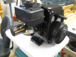
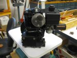
Okay, it's been a while since I last posted anything. But there are reasons. I was rebuilding that tiller engine that threw a rod and working on trolling motor and lawn mower deck as well. And around here, we've had rain for the last week or two without any let up. So I had to work between the rain and inside the shop to get anything accomplished. However, I do have a few pictures to show such things. I finally got the tiller engine finished and ready for the install on the tiller deck. But I have to paint the tiller deck still. And I did poly and CSM cover the long rod box sides to proceed with that effort too...
IMG_0005.JPG
Yes this engine is rebuilt and actually didn't cost that much. I bought new piston and rings and connecting rod and a used case. So everything was refurbished and painted.
IMG_0004.JPG
It is ready to mount again now. Just waiting for the chassis to get repainted and finished...
IMG_0001.JPG
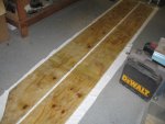
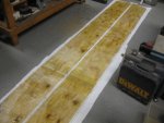
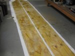
But I did accomplish work on the boat as well. I was trying to figure out where I could poly and CSM cover these rod side panels being so long. And since I wanted them to be flat, saw horses and things like that were a no go. So the shop floor was elected. But to keep from polying them to the floor. I cut up an old shower curtain and used that as a barrier on the sides. Ha, whatever works is game...
IMG_0002.JPG
And you can see the lap overs because my CSM was only 50" long but the panels were at ~12' long or longer...
IMG_0003.JPG
So now I can start working the rod boxes again. We finally have some sun popping through this afternoon...YEA!

So maybe the next progress report, I will have the rod boxes near about finished...

You all have a magnificent day... :thumb:
 

sphelps

Supreme Mariner
Joined
Nov 16, 2011
Messages
11,432
Glad you got a bit of sun ! I know we have had our share of rain and then some over the last month .. My neighbors pond will over flow and it goes like a river right through my boat work shed area .. About 3" deep ! :eek:
Motor and glass work looks great !
 

gm280

Supreme Mariner
Joined
Jun 26, 2011
Messages
14,591
Glad you got a bit of sun ! I know we have had our share of rain and then some over the last month .. My neighbors pond will over flow and it goes like a river right through my boat work shed area .. About 3" deep ! :eek:
Motor and glass work looks great !

Yes we had sun today as well. Truly amazing two days in a role now. You have to keep that rain at bay and out of your project area so you can work as well. I have mine in the shop, but I really do most of the dirty work outside to help keep the shop a little clean.

Got some more painting finished and the rod box sides polyed and CSM covered as well. So once I figure out where the floor in the boxes will sit, I can cut them for the top section and hatches. If I can get other things out of the way, I could get the rod boxes finished and flip the hull for paint prep. Always something crops up to take the time away from the boat project. But that's life. Things could always be worst...
 

gm280

Supreme Mariner
Joined
Jun 26, 2011
Messages
14,591
Yea it's been a while since I posted last. But I have been buzzy anyway. I have started work back on the rod boxes and think I finally have them laid out like I want them. I even made templates and cut the floor plates for the boxes on the starboard side. But the port side should be a mirror copy and that will make it go quick...I hope. The reason I haven't finished with the rod boxes is because I again am working on my ill neighbor's Onan 4000 Genset generator. And I mention that because once again, I come across a typical standard 30 amp relay that you can buy all over the place. Seems they look alike but are not wired alike. So make sure you buy what you really want when purchasing such a relay. The typical relays can be any one of these shown. So you really need to watch which type you buy for what you are working with. This is the second time I have come across these differences now.
0000000082508.jpg


But this is how it could be wired;

30 Amp Relay.jpg

This is the bottom view.

So I am still working on his generator for their RV (again). He is really not doing well and I am trying my best to get everything working for them so they can have some time at camping together...

The relay in question was reading about 300 to 400ohms when the contacts were closed. And that isn't a good thing either. So I removed it. And I found what was that problem. Seem these near microscopic little tiny tinny ant like insects have somehow eaten through the enclosed case and took up home there. I cut the relay open and it was amazing to see such damage between the contacts and the dirt granules those ants carried inside. The relay was toast to say the least. And I found two such relays that are wired differently but look the same. Just a heads up. Hope I can get this Generator working soon so I can get back to the boat again. But they really want to spend some time camping and I can understand their needs too. I honestly don't know how much time he has left because he is on 24/7 mega oxygen now and seriously not getting any better...

Until next post, you all have a glorious day... :thumb:
 

nurseman

Lieutenant Junior Grade
Joined
Jun 2, 2013
Messages
1,045
Nice to hear that you are able to help your neighbor. Your investment of time into your neighbors life will come back to you. Some call it karma, I call it reaping what you have sown. :thumb:
 

Camdenites

Cadet
Joined
Apr 28, 2009
Messages
26
I'm really enjoying your restoration and am very impressed with your attention to detail! I will be starting a restoration on a similar boat soon and am paying close attention to your progress. Thank you.
 

gm280

Supreme Mariner
Joined
Jun 26, 2011
Messages
14,591
nurseman, thanks for the kind words. I was just talking with my wife and telling her I was going to work on the generator again today because I think I finely found the correct schematic for his generator. Seems they changed models so many times that there are lots of schematic diagrams and you have to get the model and version release correct to see the real circuitry. So with the latest (I guess this one is correct) I'll tackle it again today. I really think they want to go camping one last time and I need to see if I can get them on their way.

Camdenites, also thanks for the nice words. I try to make certain all the little things are covered before venturing into building everything. It is a lot easier to built one time then have to rip things apart for lack of something I forgot. Does that mean I don't make my share of mistakes...NO! I do make them, and lots of them too. But think what would happen if I did try to cover everything initially. :facepalm: I also like to post the steps I use so others can tell me if they are wrong or if they are right. Then folks can learn from either my mistakes, or the successes. I mean that IS what these forums are all about. Pleasure to have you aboard and keep watching. :thumb:
 

gm280

Supreme Mariner
Joined
Jun 26, 2011
Messages
14,591
Okay some real progress. No not on the boat, but I did manage to get that Onan Generator 4000 Genset running again for my neighbor. I actually had to rework the carb again because the needle and seat were not sealing properly and the carb would eventually flood with the engine running. So I removed the carb again and took some Brasso brass cleaner and some Q-tips and polished the seat really well. I cut the Q-tips in half and used a Dremel tool to spin up the Q-tip soaked with Brasso. It worked way better then I initially thought it would. The seat actually clean up really nice. And I did that because they wanted $75.00 dollars (plus shipping) for the Nikki carb rebuilt kit. And the kit had a new needle, the fuel bowl gasket and the intake manifold gasket and air inlet gasket. That is a huge price for such few parts. So I tried the Brasso polish because the needle had no signs of wear, even with a 10 power monocular examination. I also though that maybe the fuel pump was pushing more fuel pressure then it needed. So I measured the fuel pressure and it was right at the spec of 4lbs continuously. So once I got it all back together with a new 30A relay that worked, the engine cranked and ran like it was designed. And I let it run for about 15 straight minutes looking for any other issue. The voltage was 119 VAC @ 59.95 Hz. So I think it is fixed... :dance:
 
Top