Kevin Morin
Petty Officer 3rd Class
- Joined
- Nov 7, 2009
- Messages
- 78
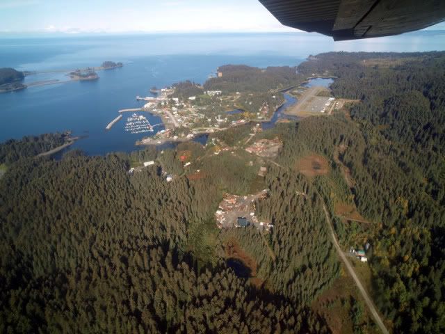
We live in the Cook Inlet in Alaska, and seasonally my wife runs a bed and breakfast in Seldovia Alaska, which can only be reached by air or water. The area has a very nice little bay extending south off of Kachemak Bay and was the site of one of Imperial Russia's original settlements in this area of South Central Alaska.
Our family has recreated in the Kachemak Bay for fifty years, including when our now thirty something children were pre-teens. During that period, our family built a little 10' dinghy for the kids and their cousins for use during our camping years, before we had a house in the Bay.

This little dinghy was rebuilt a few years ago to add new wood seats, paint and some other details.

The skiff is about 20 years old in these photos, but she cleaned up pretty well.

The bottom is 0.100" topsides 0.080" and transom is 0.125" but reinforced to hold an 8hp 2stroke leg that moves the little skiff nicely. You can see the bangs and dents from all those years with a 10 year old crew driving her onto Alaskan beaches.
Fast forward to '06, my wife and I were in Seldovia and the little skiff shown was in the harbor with our friend's family boat. We'd given the boat to a family with younger people who would use it, and one afternoon, my wife asked for the first time in 30 years if she could pilot the little blue skiff around the harbor?
Naturally, I jogged to the harbor and warmed up the engine and she spend a few hours putting around a walking speed and when she got out of the boat she said the most romantic, but kind of frustrating phrase, I can recall.
After I'd cleaned up this old skiff, remodeled and painted and given it away because none of our family would even look at it, my wife gets out of it for the first time and says; "Honey, I'd like one of those."
This thread is about the skiff I designed and built for her in the next two years in response to her new found, after thirty years, interest in having her own boat.

This is an image of the mostly complete skiff that I built to give my wife 'her new boat' to enjoy the waters around Seldovia Bay. What started with an old 10' skiff we built for the kids to pirate the rocks when we camped in K'Bay- inspired the new boat shown here.
I'd like to start with the design concept, show the construction and the finished boat more completely in the next few posts. None of the designs are for sale, these boats are not commercial products, we no longer build full time, but I hope those of you who enjoy designing and building skiffs will also enjoy reading about this one.
The 10 dinghy was built by eye but the green and yellow skiff was designed in Delftship Pro, a marine design software application with free version available, and built using that software's output.
cheers,
Kevin Morin
Our family has recreated in the Kachemak Bay for fifty years, including when our now thirty something children were pre-teens. During that period, our family built a little 10' dinghy for the kids and their cousins for use during our camping years, before we had a house in the Bay.
This little dinghy was rebuilt a few years ago to add new wood seats, paint and some other details.
The skiff is about 20 years old in these photos, but she cleaned up pretty well.
The bottom is 0.100" topsides 0.080" and transom is 0.125" but reinforced to hold an 8hp 2stroke leg that moves the little skiff nicely. You can see the bangs and dents from all those years with a 10 year old crew driving her onto Alaskan beaches.
Fast forward to '06, my wife and I were in Seldovia and the little skiff shown was in the harbor with our friend's family boat. We'd given the boat to a family with younger people who would use it, and one afternoon, my wife asked for the first time in 30 years if she could pilot the little blue skiff around the harbor?
Naturally, I jogged to the harbor and warmed up the engine and she spend a few hours putting around a walking speed and when she got out of the boat she said the most romantic, but kind of frustrating phrase, I can recall.
After I'd cleaned up this old skiff, remodeled and painted and given it away because none of our family would even look at it, my wife gets out of it for the first time and says; "Honey, I'd like one of those."
This thread is about the skiff I designed and built for her in the next two years in response to her new found, after thirty years, interest in having her own boat.
This is an image of the mostly complete skiff that I built to give my wife 'her new boat' to enjoy the waters around Seldovia Bay. What started with an old 10' skiff we built for the kids to pirate the rocks when we camped in K'Bay- inspired the new boat shown here.
I'd like to start with the design concept, show the construction and the finished boat more completely in the next few posts. None of the designs are for sale, these boats are not commercial products, we no longer build full time, but I hope those of you who enjoy designing and building skiffs will also enjoy reading about this one.
The 10 dinghy was built by eye but the green and yellow skiff was designed in Delftship Pro, a marine design software application with free version available, and built using that software's output.
cheers,
Kevin Morin
Last edited:


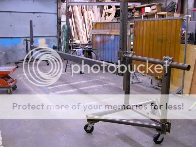
 avis Skiff Jig