1970 Bell Boy Bonneville project

fiberformbl

Cadet
Joined
Nov 14, 2010
Messages
15
Hello,

I joined this forum a few years ago when my Fiberform 17 ft open-bow tri-hull cracked its transom. Investigation showed that the transom and stringers were rotten - all the wood in the boat needed to be replaced - big job. I pulled the cap and started demolition, but then quit and it has been sitting for years - I recently came to terms with the fact that I would never finish this project, but I wanted to get back on the water (without spending a fortune). I had a trailer and an outboard motor, so I started looking for hulls that might work. Since I was looking at cheap stuff, the chance of rotten wood was high, so I was drawn to boats that were made without (or with less) wood to rot. And after having a tri-hull and realizing how bad it is in even a little chop, I wanted a V-hull.

I came across this Bell Boy Bonneville for $10 - no wood in the stringers, and the transom was really solid. So this is my new project. I read Pusher's post on his Bell Boy restoration - he did a great job on the restoration and the description, and much of what he did fits my thinking too. My boat even has the same color scheme as Pusher's, but is a little longer at 19.5 ft.
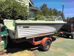
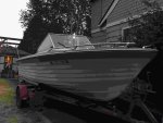
BellBoy01.jpg BellBoy02.jpg

I will try to contribute by posting photos of the work, but I REALLY hope to get input from people on fiberglass work and engine controls - I will start posting soon. Maybe a little unusual, I am going to get this in running shape first and then go back and fix things up. This is in part because I want to be on the water, and in part because my wife wants me to prove that it floats before I invest any money in fixing it up - of course it will float, but I suppose she is challenging me to get it working after our other boat sat broken for six years. Whatever - I want to be on the water so I will humor her. Some questions coming up soon about Bell Boy structure, since floor deck is already removed and will be one of the first fixes.
 

ezmobee

Supreme Mariner
Joined
Mar 26, 2007
Messages
23,767
Well I personally would have gone for an aluminum hull but that one looks pretty decent if it indeed doesn't have any rot. It'd be pretty unusual for a glass hull that old that's been sitting out to not have rot. The deck and transom are surely wood.
 

fiberformbl

Cadet
Joined
Nov 14, 2010
Messages
15
Yes, aluminum would be a sure-fire solution to wood rot. Not sure that I could find one cheap, but maybe someday I can spend the money for a great aluminum boat. But for now, I think that this one is solid and I hope that I can keep it that way. It has no holes in the transom except for two motor mount holes, drain plug, and splash well drain (and two tie-down anchors but they are high on the transom). In any case, the transom seems solid, and I plan to seal the deck all the way around, with drainage to the transom well, sealed against stringers there. I already have some questions - some Bell Boy specific, some more general.

General
  1. The floor was removed by the previous owner about a year ago, but boat was covered most of that time. I want to check the foam to make sure it is dry (need to do this between each stringer and maybe at two or more spots). Any tips for creating a tool to pull core samples of under-deck foam? Any reason to replace the foam if it is dry (and I plan to completely seal the deck)?
  2. What type of resin should be used to bond to the original fiberglass (assuming polyurethane rather than epoxy, after sanding of course)?
Bell Boy
  1. There are recesses in the stringers near the stern (you can see them in the photos from Pusher on 1970 Bell Boy runabout restoration) - I want to completely seal the deck so that is has no access to water, so I would want to fill these gaps. Did these cutouts have a purpose (something for drainage or for some optional feature like a gas tank mount?) and if they can be sealed completely?
  2. Are there any sources to buy trim parts for these boats (like the aluminum cover for the transom cover)?
More questions to come.
 

Woodonglass

Supreme Mariner
Joined
Dec 29, 2009
Messages
25,927
What have you done to ensure the Transom and Stringers/Bulkheads are OK?? You can make a Foam Core sampler from a piece of 2" PVC cut some teeth in one end a drill a 1/2" hole in the other. Stick a Large screw driver thru the hole and"Drill" down through the foam til you hit the hull..
 

fiberformbl

Cadet
Joined
Nov 14, 2010
Messages
15
Woodonglass, thanks for the tip on drilling the foam - I will do exactly that. For the transom, I am ashamed to say that I have not done anything very serious to check it - banged all around with the end of a screwdriver listening for hollow sound, inside and outside, 2) poking around at the wood in the 2 existing motor mount through holes, and 3) mounting my motor and using it as leverage while looking for flex. I have not drilled it. I will likely dig out the foam at the back to get a full view. Fortunately the deck is (was before previous owner cut it out) fully glassed in except where it drains into the drain well at the stern, so it might have been good about keeping dry among the stringers. I suppose I could carefully drill the interior fiberglass just down to wood and poke it, then glass it over. Any other tips for checking? At this point it would be for peace of mind at least.
 

fiberformbl

Cadet
Joined
Nov 14, 2010
Messages
15
No Title

Ok, so I cored the foam in a few places using Woodonglass' recommendation, almost. I had a 1.5 inch aluminum pipe on hand so sharpened it and made some tough cutting edges. I had some trouble getting the core to pull out of the hole - maybe this is why Woodonglass said a 2 inch pipe - it would make it easier to pull a stubborn core. Top foam was white and clearly fluffy and dry. I got all the foam from a hole near the rear - near the bottom the foam changed, it was more yellow (top foam was white), but I could not tell if it was wet or not - definitely no standing water and foam not soggy wet, but it was different somehow, and heavier (I am talking about the bottom 1/4 inch or so, and in my hands I could not tell if it was wet or not). So, I put some of the suspicious bits in a sandwich bag and hit it with the microwave for a about thirty seconds - the result is shown in the photo - looks like water condensation. So, I guess there is some water down there, although not much, I don't know how extensive and don't like the idea of sealing up the deck completely with some wet foam down there. So, I will probably start in the most suspect areas and cut out sections of foam until I find dry areas or pull all the foam, whichever comes first.
 

Attachments

  • photo273775.JPG
    photo273775.JPG
    345.4 KB · Views: 0

fiberformbl

Cadet
Joined
Nov 14, 2010
Messages
15
No Title

I missed these photos in the post above.
 

Attachments

  • photo273781.JPG
    photo273781.JPG
    319.6 KB · Views: 1
  • photo273783.JPG
    photo273783.JPG
    330 KB · Views: 1
  • photo273784.JPG
    photo273784.JPG
    386.5 KB · Views: 1

fiberformbl

Cadet
Joined
Nov 14, 2010
Messages
15
No Title

Ok, motor mounting questions (temporarily because I am pushing to get the boat sea-worthy, then will go back for repairs and sprucing). It is 1978 Mercury 800 (80 hp). There are two original motor mounting through holes in the transom, and marks from the old clamps - this had a Mercury "tower of power" 115 hp on it before. My motor has four mounting holes - the extra two are at the very top near the clamps. To make the motor fit, I had to raise the yoke 1/2 inch above the transom, which unfortunately puts the upper holes nearly at the lip of the transom cover strip. I rested the yoke on a piece of 1/2 inch plywood rather than leave it suspended (see photo). I was planning to go without the upper bolts temporarily while I figured out everything else, but I wonder if I can do without them - the metal around these holes is not very beefy, and I wonder if they were intended to offer much structural strength - they are so close to the clamps that it seems the clamps would be sufficient (and much beef-ier). Also, this puts the anti-ventilation plate about 3/4 inch above the line that extends backward from the bottom of the boat. I have read that the anti-ventilation plate should be +/- 1/4 inch of this line, except to add 1 inch for every 12 inches that the motor is behind the transom - mine sits about 6 inches back, so that would put the recommendation at +1/4 to +3/4 inch above the line, and mine is at +3/4 inch. Can I leave it at this height, and can I run just the lower two bolts, not the upper two (only clamps at the top)?
 

Attachments

  • photo273785.JPG
    photo273785.JPG
    305.3 KB · Views: 0

Pusher

Lieutenant
Joined
Sep 2, 2014
Messages
1,273
Haha, I'm pretty sure my wife used language along the same lines... Prove that it actually floats :)

By the way, I am a little jealous of the 19.5'. That extra 2" would be ideal! No more, no less.

General
#1 I would dig the foam out up to the bow. If you replace it, that will probably be the cheapest part. Mine was soaked underneath. I lost a lot of weight digging it out.

#2 What kind of budget are you on?

Bell Boy
#1 are you referring to where the fual tank and battery are in post #1? If so that was an under floor fuel tank that had a hanged door. I can't remember where I saw this. There's a facebook group out there that is for Bellboy owners only. I only have FB for messenger, so I am not a member.
http://forums.iboats.com/forum/boat...264220-1971-17-bell-boy-runabout#post10264220

#2 You've got me stumped on that one.

Post #5
You'll be drilling new holes for the motor and I'm guessing a kicker bracket, so you'll see how the transom's doing at that point. If water intruded from the iterior it would likely rot from the low points. If it leaked from the splash well/transom trim, then it would have rotted from the top down. That's why some are very adamant about test drilling all over. Some people have found out the hard way.

Watermann shared a slick drill guide which I purchased and used to drill my transom bolts straight. I would highly recommend it.

https://www.google.com/search?q=dri...LysvVAhWD7oMKHae9B-sQ_AUIECgB&biw=360&bih=559
 

fiberformbl

Cadet
Joined
Nov 14, 2010
Messages
15
No Title

Hi Pusher! thanks for coming over to this thread and for the tips.

General
#1 Thanks for the tip - I probably will do that (wife is going give me a hard time about that).

#2 For budget, I want to do it right and save effort/time where possible, but not be extravagant with spending.

Bell Boy
#1 yes, I was referring to top of the stringers near the drain well at the stern - they can be seen in your image (reposted here with arrows) - a photo of mine is posted here too but you can't see the cutouts in the photo because the floor covers the top of the stringer. I am wondering if these have some functional purpose that I should be aware of. but I am guessing that they are there for some other setup - like the inboard/outboard motor mounting.

Bell Boy Facebook page: They shut that down recently but started a "group". I have posted there too - lots of people have seen it but no responses at all - y'all are doing better for me than they are - probably have to buddy up more to get responses there. Thanks to Woodonglass and ezmobee for looking and writing.

Post #5: Yes will be drilling for kicker bracket at some point, but hoping to not re-drill for main motor (see Post #8) - it would be about 1/2" from the existing holes. But I will probably remove foam all the way to the transom (and all the rest as you suggest) and test drill then since after foam and deck most of the transom would be inaccessible and I would always wonder about the condition.

Drill guide suggested by Waterman: Yes! I have been wondering how to do it right - I will look at the guide.
 

Attachments

  • photo273855.jpg
    photo273855.jpg
    214.6 KB · Views: 3
  • photo273856.JPG
    photo273856.JPG
    325.8 KB · Views: 3

Pusher

Lieutenant
Joined
Sep 2, 2014
Messages
1,273
No problem, pleasure to be aboard!

yes, I was referring to top of the stringers near the drain well at the stern - they can be seen in your image (reposted here with arrows)

Oh I see what you mean now. I assumed that was where a doubler support attached to the underside of the hinged lid that sat over the fuel tank.... I've never figured it out myself either though.
 
Top