Starcraft Holiday senior project: Convert to twin Jetski drives

jbcurt00

Moderator
Staff member
Joined
Oct 25, 2011
Messages
24,871
Not at all familiar w jetski motors and jet setups, but is the efficiency of the system, water turbulence at the intake grate and output of the nozzle affected when installed canted?

Whats the hull shape at the transom on typical twin jet setups?

Are those the intake grates where the jet sticks out past the transom? Or are they further forward in the stuffing boxes between the transom and motors.

TIG work on the motor mounting looks good. Nice work
 

Tnstratofam

Commander
Joined
Aug 18, 2013
Messages
2,679
Are the base plates for the motor mounts welded to the ribs in the hull or riveted?

The welds look great by the way. Nice fabrication work. :thumb:
 

drev500

Seaman
Joined
Aug 31, 2015
Messages
61
Not at all familiar w jetski motors and jet setups, but is the efficiency of the system, water turbulence at the intake grate and output of the nozzle affected when installed canted?

Whats the hull shape at the transom on typical twin jet setups?

Are those the intake grates where the jet sticks out past the transom? Or are they further forward in the stuffing boxes between the transom and motors.

TIG work on the motor mounting looks good. Nice work


JB, there should be little to no effect of the pump efficiency when installed as such. I shared a picture before showing a company that manufactures twin jet drive boats with the pumps mounted on each side of the keel following the deadrise. Performance was not sacrificed when installed. It is important for jet drives to not have obstructions at least 3 feet (roughly) in front of the intake. A smooth hull in front of the intake and subtle intake geometry are key to pump performance. Unfortunately, we are unable to perform test models due to time and money. We did lots of research of what to do and what not to do although such a platform has yet to be performed on this boat so time will tell but I do feel very confident.

The intakes due stick out 4 inches past the transom. We did this due to space limitations. The whole jet drive from nozzle to front of engine is a little over 5 feet. We have 2 feet of that aft of the transom. I believe this will work and having consulted with others who have more experience with jet drives have shown me where a system like this was incorporated for the same reasons. Again, ensuring that the wetted surface ahead of intake is smooth and free of obstructions will ensure proper performance.
 
Last edited:

drev500

Seaman
Joined
Aug 31, 2015
Messages
61
Are the base plates for the motor mounts welded to the ribs in the hull or riveted?

The welds look great by the way. Nice fabrication work. :thumb:

Dave!

So the base plates are riveted with some 1/4" closed head aluminum rivets. In our shop we only have a tig welder which for my limited time on the tig torch doesn't allow for confident welds. I believe the rivets to be substantial but I am open to constructive criticism. I am hoping with these posts for people to point out some mistakes that are less obvious to us.

Thanks!
Evan
 

Tnstratofam

Commander
Joined
Aug 18, 2013
Messages
2,679
The rivets may be okay. The biggest concern I would have is metal fatigue caused from the torque of the two motors on the ribs so close together. I believe that most inboards use a more substantial anchor over rivets, Using the motor mount set up you have I would keep an eye on the rivets to be sure they don't come loose during engine operation over time. So long as they don't start to loosen they should be good.


Unfortunately I don't have a good substitution right now, but I'll put my thinking cap on. Maybe I'll think of something else in the event they do start to come loose.
 
Last edited:

jbcurt00

Moderator
Staff member
Joined
Oct 25, 2011
Messages
24,871
I/Os have a box beam of aluminim, filled w wood, for motor mounts, riveted down on both sides of the box beam.

So either side of the same mount is relatively close together, but the other side of the motor's mount is fairly far away on the other side of the keel.

Arent those Rotax motors? How is motor torque applied to the mounts on a Rotax motor?

dozerII
Watermann

Both did modified I/O builds
 
Last edited:

Tnstratofam

Commander
Joined
Aug 18, 2013
Messages
2,679
I guess I'm just overly cautious. I have worked with sheet metal for a few years in the heating and air industry, and know that if you put the right amount of torque in the right spot enough times it will cause the metal to weaken and crack or break. In this case I believe the weak link would be the rivets themselves. It seems like they are the focal point of the stress.

I could be completely wrong and everything may be fine, I'm just a little concerned with only three rivets on either side of the engines being all that secures them to the hull. It looks like the only real option though so I would carry on as you are.

Again not trying to stir the pot. Just thinking out loud.
 

TruckDrivingFool

Lieutenant Commander
Joined
Jul 30, 2007
Messages
1,818
In my uneducated eyes I'd worry more about damage to the hull skin due to the stresses being transferred to the hull by just three ribs and not spread out along the entire thing by the stringer type of setup that JB mentioned. Beyond that I do share TNs fears of that few pop rivets for that kind of structural use.
 
Last edited:

drev500

Seaman
Joined
Aug 31, 2015
Messages
61
I guess I'm just overly cautious. I have worked with sheet metal for a few years in the heating and air industry, and know that if you put the right amount of torque in the right spot enough times it will cause the metal to weaken and crack or break. In this case I believe the weak link would be the rivets themselves. It seems like they are the focal point of the stress.

I could be completely wrong and everything may be fine, I'm just a little concerned with only three rivets on either side of the engines being all that secures them to the hull. It looks like the only real option though so I would carry on as you are.

Again not trying to stir the pot. Just thinking out loud.


Dave,

Not stirring the pot at all. This is what I had intended with this thread is some outside thinking. We do plan on placing some weld beads on the ribs to ensure 0 creep. We will also be periodically checking the mounts to ensure they have not moved.

We did place 6 rivets on each mount base, two in each rib for a total of 12 rivets per engine. These 1/4" rivets have a tensile strength of 1100lbs and 900 shear. So long as the rivets don't stretch, there is plenty of holding strength.
 
Last edited:

drev500

Seaman
Joined
Aug 31, 2015
Messages
61
In my uneducated eyes I'd worry more about damage to the hull skin due to the stresses being transferred to the hull by just three ribs and not spread out along the entire thing by the stringer type of setup that JB mentioned. Beyond that I do share TNs fears of that few pop rivets for that kind of structural use.


Truck,

We did run a FEA (Finite Element Analysis) program on the engine mounts in our CAD software and it came out very well. FEA is basically a little program you can run on a design environment where you specify the material and the type of load at certain point(s). It will show you potential structural issues within the given system.

With the port engine semi bolted in, it confirmed our FEA results with a very solid engine structure. These motors are only 120 lbs each which lessens the shock load going of waves and such.
 

drev500

Seaman
Joined
Aug 31, 2015
Messages
61
I/Os have a box beam of aluminim, filled w wood, for motor mounts, riveted down on both sides of the box beam.

So either side of the same mount is relatively close together, but the other side of the motor's mount is fairly far away on the other side of the keel.

Arent those Rotax motors? How is motor torque applied to the mounts on a Rotax motor?

dozerII
Watermann

Both did modified I/O builds


JB, these are Yamaha Motors 1100cc 3 cylinder 2 strokes to be exact. They are basically the same at Rotax (operating wise) but they do differ by how they are connected to the jet pumps.
 

Tnstratofam

Commander
Joined
Aug 18, 2013
Messages
2,679
You're allready ahead of the game while the rest of us are playing catch up so to speak.:encouragement:

Glad to hear you are putting so much thought into the design process.
 

NorthwestChap

Petty Officer 1st Class
Joined
Mar 7, 2011
Messages
224
Dave,

Not stirring the pot at all. This is what I had intended with this thread is some outside thinking. We do plan on placing some weld beads on the ribs to ensure 0 creep. We will also be periodically checking the mounts to ensure they have not moved.

We did place 6 rivets on each mount base, two in each rib for a total of 12 rivets per engine. These 1/4" rivets have a tensile strength of 1100lbs and 900 shear. So long as the rivets don't stretch, there is plenty of holding strength.

What a cool project. Hope it all comes together for you.

I'm a bit sketchy on where you are talking about placing the weld beads. Maybe that will make the rest of this no longer moot. I too am a bit concerned with the rivets and their ability to hold long term. Just a few things to consider... Lateral loads due to sharp turns, maneuvering, and wakes will be a factor, as I'm sure you're not gonna be going in straight lines with two healthy jets behind you. Now you have the weight of the engine acting as a lever on 6 of the rivets. I'm not familiar with the type and guage of the aluminum in the ribs, so is pull-out strength of the rivets in the ribs a factor? What about vibration and it's effect on the rivets?

Your periodically checking would be wise, maybe consider it like an AD (airworthiness directive). In the short term it will probably be sufficient to get you that A for the project.
 

Old Mud

Cadet
Joined
Sep 20, 2013
Messages
13
Drev, i would have considered bedding for those rivets, But as you have them already installed maybe just a bead around the heads and inside the mounts around the area where the rivets are. 5200 by 3 M would be good, it will adhere to aluminum and give flexibility where anything solid will break from the lack of elasticity..My feeling is you need some flex in there to compensate for vibration .

That stuff is the best marine sealant for permanent applications. I have been using it for many years and have done a many tests with it. .It will not harden to a solid mass, it keeps flexible.. Just a thought for your consideration , i have no stock in 3M but like their product. .
 

dozerII

Admiral
Joined
Oct 25, 2009
Messages
6,527
I too am a little worried about the mounts just contacting the three hull ribs. Two three cyl engines could cause some serious harmonic vibrations that the aluminum won't like. I am pretty sure that is why StarCraft uses fairly substantial wooden masses to help absorb these vibrations. Most all are fastened with solid rivets to the hull using the same rivets that attached the ribs, not just to the rib. You may want to look at building two outboard laminated ply stringers for the outer mounts and a large center one as a common mount for both inboard ones. JMTC's

Very cool project by BTW
Here's a couple photos of the mounts used for the V6 in my SS201


Last edited:

drev500

Seaman
Joined
Aug 31, 2015
Messages
61
After much deliberation and input from you guys, we are going to change the motor mounts. The last few days we have spent a lot of time and pondering on the subject. The idea of getting a horizontal mounting plane is easy but with two engines it is very difficult to get a solution with a limited budget.

After our quiz in our last major thermal class today, our team met up to discuss the dilemma. Everyone's input has helped out in the decision. We took the input of lack of mounting structure with rivets on the ribs and input in a new mount idea (dozerll thank you for the pictures). I have learned from classes that no idea is bad idea. Even the most absurd solutions can have some positive effect on the final outcome.

In our young minds, there is a lot of learning involved with this project and some trial and error. This is definitely our first biggest learning experience. A lot can be conceptualize that sounds like a sound solution but when implemented isn't. This first go was it.

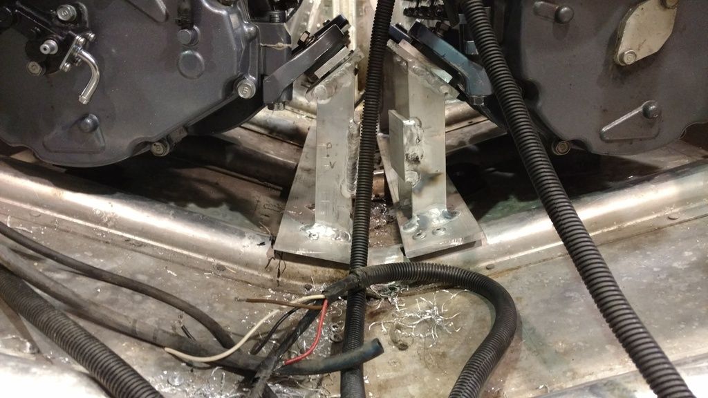
I feel that this picture shows what we were up against. A simple problem with "many ways to skin a cat" for a solution." This is looking the down the keel towards the stern. The multiple angles with the engine cradle and the hull offer difficulty for a simple install. Also, the long struts allow for a lot of movement (deflection) forward and aft. When the engines are bolted to the mounts they are solid but with repeated shock loads, there is a chance with poor welds( I've only been on the torch for a few hours) and potential for rivet creep with the low amount of rivets. This could cause an undesired outcome with motors becoming lose anchors...


No matter the amount of FEA we do on the system, we are uneducated on the potential shock loads that can be subjected to the motors when going over waves and what not. I believe it is something that can be learned with experience and going to a designated marine engineering school; both none of us on the team have. Fortunately, we have this thread and everyone who is participating who have the experience and better know-how.

Two reasons we are going to a new design; unknown effects on current design during service life and alignment issues. The first everyone who has commented with concern understand but the second is something I haven't brought up. With the current design, alignment with the jet pump coupling is done with the engine mounts. As the engine mounts are on an angle, it can be aligned but with lots of confusion since when a shim is added it will the motor up and over with relation to where the shim was added. If the motor is needed to only move horizontally then this is unachievable since the motor will move at a diagonal motion. It isn't a complicated issue but something that is challenging when fabricating skills lack (precision lacks heavily with limited tooling and skills). For mostly of the first reason, we have chose to move on from this.

We are going to incorporate the box mount dozerll had illustrated. We thought about the idea at first but didn't think much about it. We tried to research current implementation but had a tough time finding pictures like the ones dozerll showed (thank you again). Luckily we have a brake press that I used to build the pump boxes that will aid in this fabrication. I will show more about this next week when fabing starts. Our idea is basically the same as what is shown in his but with a common box in the keel area shared with both port and starboard engines.

Dozerll, can you share with me more about the mounts you showed? Where does the wood in the first picture go? On top of the box I assume? What type of material (we are going to use aluminum and I assume what you shared is the same) and what is the thickness?

Again, we really appreciate everything everyone has contributed to this project. It has been an amazing project so far to learn from and the enjoyment is priceless. I look forward to the coming months when we all get to see it make its first big SPLASH with the drive setup. :D
 
Last edited:

64osby

Admiral
Joined
Jul 28, 2009
Messages
6,799
Don't know how much tolerance you have with your present mounts, another option might be to add a plate under your current plates attached to the ribs and use a dampener between the two. Much like motor mounts on automobiles.

It would eliminate the vibration stress to the rib rivets.

Just my .02.
 

jbcurt00

Moderator
Staff member
Joined
Oct 25, 2011
Messages
24,871
I dont know what guage they are but the motor mount boxes are aluminum. The wood goes inside the box mounts.

The boxes are notched over the ribs and are thru riveted to the hull between each of the hull ribs. IIRC, there are additional ribs that only extend to (into?) the boxes.
 

dozerII

Admiral
Joined
Oct 25, 2009
Messages
6,527
Yes a JB said the two aluminum boxes are riveted to the hull skin not the ribs as you can see in the second picture. The wood was inside the boxes. The motor which was a 206hp GM V6 was lag bolted through the aluminum to the laminated wood. You could do the same with your center mount. Break some heavy gauge aluminum to the correct angles and width for both motors forming a box, maybe you could make this box long enough to tie into the transom as well? Laminate some exterior ply together oversize for the box, then cut it on a table saw to fit the angles of the inside of box, this will be super strong and absorb all those nasty vibs
 

Grandad

Lieutenant Commander
Joined
Jun 7, 2011
Messages
1,504
Hi Drev. I've been silently watching with great interest, having no experience in jets. A closer look at your library of pictures caused me to become concerned. Perhaps you're way ahead on this, particularly since you've already done a stress analysis, but speaking up later will be no help. I thought that these engines would be stabilized by the transom and it would be communicating the torque of the prop shaft to the blocks, but now realize the plan doesn't appear to use the transom as a substantial component. If it's not already too late, perhaps you could consider that in your new engine supports.

As seemingly strong as the motor bed that Dozer has pictured is, the bed designed originally by Starcraft really only supports weight and aligns that big chunk of iron. As strong as it is, it still isn't required to take torque from the prop shaft. In most I/O's that's taken up by the thick plywood transom that's clamped between the outdrive and the engine, making the assembly all one very strong element. As I see it now, because of a separated output shaft, your aluminum hull skin has to take the torque. And if you're not planning to replace the plywood in the transom at all, the aluminum skin is also required to take the pressure of the forward thrust of the jets. Do these jet engines normally take the thrust directly or is there a packing block with a thrust bearing of some sort provided in their original craft? Anyway, if your new mount could include a structural connection to the outdrive via a strong transom, the forward rivet connection becomes much less critical. - Grandad
 
Top