Jack plate help.

bonz_d

Vice Admiral
Joined
Apr 22, 2008
Messages
5,276
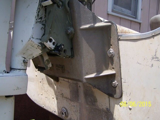
The 1984 Sea Nymph FM144 I recently purchased came with a Mini-Jack jack plate. The boat has a short transom with the jack plate added for a long shaft. Also this boat must have had a Merc on it because those are the controls that were in it.

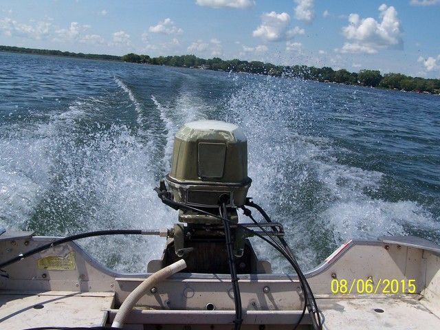
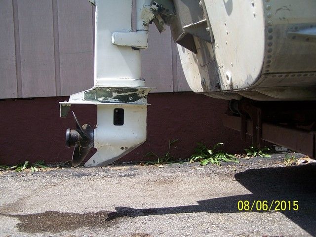
I have installed a 1994 30hp Johnson long shaft on it and am getting horrible performance. Boat takes forever to come up out of the hole and while it is the bow is very high. Below 1/2 throttle the stern drops again and the bow comes up. When running at 3/4 or better throttle it is producing a very high spray from the lower unit. I believe the engine is still too low and causing the problem.

Thing is that I have never worked with a jack plate before and have no clue. This plate has a 4" setback. Mounted with 4 bolts thru the transom and while I 1st thought there were other holes to move it up or down there are not. So I don't want to just start drilling more holes in either the plate or the transom before I get an idea as to how to adjust this.

Thanks, here are a few pictures for reference.


Woodonglass

Supreme Mariner
Joined
Dec 29, 2009
Messages
25,927
To me, it looks like the Jack Plate is incomplete. You need a another plate to mount the motor on that would have slot in it, that WOULD allow you to move the motor up and down to various heights. I'd recommend fabricating a plate from two pieces of 3/4" plywood and treated with the Old Timers sealant and painted with Rustoleum. Here's how to adjust the motor to the correct height. Basically the cavitation plate should be even with the bottom of the keel +- 1 1/2" -2": You're not THAT much off (Deep) but I've been told it's better to be a little High than too deep!!!. Here's a link to plans for a Shop Built Jack Plate that kinda shows what I'm saying...

http://www.dillon-racing.com/jackpla...te-page-01.htm


0Z41WB6-1.gif
 
Last edited:

gm280

Supreme Mariner
Joined
Jun 26, 2011
Messages
14,604
Actually that isn't so much a jack plate as it is merely a set back plate. The usual jack plates can be adjusted quite easily and has a fairly good range of movement. So seems you have a one fixed mount setback plate. It looks like you need to go up about a inch or more to solve your problems. I had an adjustable jack plate on my bass boat and can tell you when you get the engine set properly, it is amazing how well it handles and the top speed you'll gain...
 

bonz_d

Vice Admiral
Joined
Apr 22, 2008
Messages
5,276
Yes this is a TH Marine Mini Jacker. Not really an adjustable jack plate but from what I've been reading it looks as though this is mainly meant to use a long shaft motor on a short shaft boat. Then by adding the additional setback the motor normally needs to be higher yet. Now I need to figure out how much higher.

In the last picture you can see dimples in this which are supposed to indicate where to drill for the mount to transom. Those dimples are on 1" centers.

Still reading and learning, thanks for the replies. Oh, one of the things I've read is that the engine should be raise appx. 1" for every 6" of setback. Don't know if this holds true for these smaller boats.
 

gm280

Supreme Mariner
Joined
Jun 26, 2011
Messages
14,604
bonz_d I think the reason for the raise an inch for every 6" setback was because as the water comes off the lower hull section. it is angled upward. So I can understand that. I would see if you could find another aluminum plate (1" thick would be great) to mount the engine on and raise it up higher. I think you will be impressed at the results. JMHO!
 

bonz_d

Vice Admiral
Joined
Apr 22, 2008
Messages
5,276
Right now I'm thinking of pulling it off and drilling to that lowest hole position which would raise it 1" Right now it measures about 1.25" below the bottom.
 

lckstckn2smknbrls

Lieutenant Junior Grade
Joined
Sep 18, 2008
Messages
1,114
I used a couple of pieces of wood on top of the transom or in your case on top of the mini jacker to find the height you need. I have a 1436 jon with a '81 mariner 25hp motor that is about 2" above the bottom. It jumps out of the hole and is fast.
 

bonz_d

Vice Admiral
Joined
Apr 22, 2008
Messages
5,276
I used a couple of pieces of wood on top of the transom or in your case on top of the mini jacker to find the height you need. I have a 1436 jon with a '81 mariner 25hp motor that is about 2" above the bottom. It jumps out of the hole and is fast.

From the reading I've done so far on these plates it is not recommended to do that. So being unable to find any definitive answers on how these are supposed to be mounted and set up for the correct height I've decided I'm going to remove the engine and drill the plate for the lowest holes which will raise it about 1". Figure I'll find it either worked or it didn't or is unusable in that position because the mount has become unstable or is causing too much stress on the transom.
 

bonz_d

Vice Admiral
Joined
Apr 22, 2008
Messages
5,276
As mentioned in my other thread I did move the engine up 1" which helped but did not fit the problem. Still too low and still getting spray. Looks to me like it still needs to come up another inch which isn't there. Also think the 4" setback is contributing to this problem. The length of the original transom is 16" and the measurement now from the bottom of the boat to the top of the mount is 21"

So now I am uncertain as to how I'm going to proceed. Try and build a different plate with less setback, rebuild the transom and raise it 5" or start looking for a short shaft engine. Regarding the last solution, I did a search late last night of a 200mi area and there are no 30/35hp outboards available right now let alone one with a short shaft other an 2 shorts I found that neither of them run.

So much for this being a quick project to get back on the water!
 

gm280

Supreme Mariner
Joined
Jun 26, 2011
Messages
14,604
bonz_d, not sure what you have available at your disposal, but here is a really easy way to make your very own adjustable jack plate. All that is really involved is some elbow grease and I think you have some of that left yet... And this can be custom made and/or altered to fit your needs. And if I'm not mistaken, I think this was posted on here once before. I had ideas to built one myself and finally got all the materials I'll need for free. My son came through with such things.

http://www.dillon-racing.com/jackplate/plans/jack-plate-page-01.htm
 

bonz_d

Vice Admiral
Joined
Apr 22, 2008
Messages
5,276
Thanks gm, Yes that has been suggested and I have looked at it. Just a little uneasy about having to move this engine up even further. It's already starting to look like a hydroplane and not real certain as to how much this transom can withstand by changing the geometry. Will say I'm about ready to call the season a wash and just move on to either completely rehabbing this one or put it aside and finish the Alumacraft and have it ready for spring.
 

gm280

Supreme Mariner
Joined
Jun 26, 2011
Messages
14,604
Thanks gm, Yes that has been suggested and I have looked at it. Just a little uneasy about having to move this engine up even further. It's already starting to look like a hydroplane and not real certain as to how much this transom can withstand by changing the geometry. Will say I'm about ready to call the season a wash and just move on to either completely rehabbing this one or put it aside and finish the Alumacraft and have it ready for spring.

bonz_d, I understand what you are saying. If you decide to make such an adjustable jack plate for that transom set up, make both pieces longer then usual. And then that way you can install it with a longer reach. In other words you can install the longer sections and gain the strength from having it bolted down lower on the transom. That would allow the engine to apply its force to the lower transom area as well as upper area for better strength. And the longer section that bolts to the engine itself can have a stronger support also. So the transom would have the total torque spread out over a much larger area. Just an idea. :noidea:
 

bonz_d

Vice Admiral
Joined
Apr 22, 2008
Messages
5,276
gm, thanks for the help and suggestions. Still trying to figure this out. The transom is 16" deep and I now have the engine raised 6.5" above that and it is now even with the bottom. I've never heard of a 22.5" transom. And from what I've read about setbacks is that with 4" of setback I'd still need to go up another .5 to .75" inch to get it up out of the water.

I have been thinking of making a simple one, non-adjustable with no setback. I have some 1.5 X .125" Stainless angle and just concerned if it will be strong enough. One of the problems I'm going to run into is the structural part of the transom inside the boat is only about 1" below where the bottom bolts go thru. Below that is only the single sheet aluminum of the hull. But I understand your idea.
 

bonz_d

Vice Admiral
Joined
Apr 22, 2008
Messages
5,276
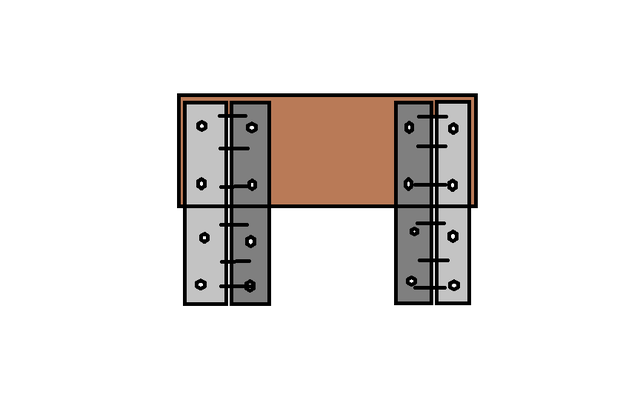
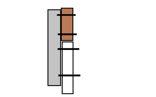
Well folks I haven't given up.. Came up with an idea after looking at the dillion-racing model and a few others I've found on-line like this http://www.theonlinefisherman.com/forum/index.php/topic/13203-how-to-build-your-own-jackplate/ and thought I'd run it past all you home engineers to see what you think. Please pardon my attempt at MS paint.


What I'm looking at using is a mix of stainless angle and aluminum angle that I can obtain locally. The stainless I already have. The one I linked to suggests using 3" X 3" X.25" aluminum but again is then using a 4.5" setback. While I'm going to try and eliminate the setback and just raise the engine.

So what I have and am thinking of trying to use is 1.5 X 1.5 X .125 stainless with the same dimension aluminum bolted together as shown in my primitive pictures. The dark gray being the stainless and the light gray being the aluminum, the brown being the wood and the white the transom.. I'm thinking the stainless will provide more strength and rigidity than the aluminum

So tell me what you think, honestly. I won't be offended if no one thinks this will work.
 

gm280

Supreme Mariner
Joined
Jun 26, 2011
Messages
14,604
Well folks I haven't given up.. Came up with an idea after looking at the dillion-racing model and a few others I've found on-line like this http://www.theonlinefisherman.com/forum/index.php/topic/13203-how-to-build-your-own-jackplate/ and thought I'd run it past all you home engineers to see what you think. Please pardon my attempt at MS paint.


What I'm looking at using is a mix of stainless angle and aluminum angle that I can obtain locally. The stainless I already have. The one I linked to suggests using 3" X 3" X.25" aluminum but again is then using a 4.5" setback. While I'm going to try and eliminate the setback and just raise the engine.

So what I have and am thinking of trying to use is 1.5 X 1.5 X .125 stainless with the same dimension aluminum bolted together as shown in my primitive pictures. The dark gray being the stainless and the light gray being the aluminum, the brown being the wood and the white the transom.. I'm thinking the stainless will provide more strength and rigidity than the aluminum

So tell me what you think, honestly. I won't be offended if no one thinks this will work.

It could work. But I would certainly run the support metals down the transom further then original because that moves the torque point move to the lower section of the transom. If you could find some quality thicker box metal, you wouldn't need anything else but that. Two box sections cut to install the engine and bolt to the transom would solve everything. I mean all you are trying to do is build something to make the transom higher while sporting the engine... JMHO!
 

bonz_d

Vice Admiral
Joined
Apr 22, 2008
Messages
5,276
I understand your thinking about running the supports farther down the transom, the thing is that the transom board on the inside is only 7" deep so below that there wouldn't really be any added support. I suppose I could add a small pcs of wood or flat stock to spread the load of the bold.
I can also get 2 X 2 X .125 aluminum angle which would spread the load area another inch just not sure if it would hold up to the bending force although I could and another pcs of angle to the inside from the top transom bolt to the lower wood bolt.
 

Woodonglass

Supreme Mariner
Joined
Dec 29, 2009
Messages
25,927
This is exactly what I was suggesting in Post #2!! Guess I did a poor job of explaining it!!!:eek:;)
 

bonz_d

Vice Admiral
Joined
Apr 22, 2008
Messages
5,276
No WOG I was just being stubborn and stupid. I think what it was is that I saw the setback on the one in the link and said to myself that's not what I want.

Well all I can do is try the way I drew it up and see if it works. At least to raise it to where I want it. Then if I have to I can get heavier material and beef it up.
 

bob johnson

Rear Admiral
Joined
Feb 25, 2009
Messages
4,306
couple things.... how many bolts are holding your motor to the mini jacker?? I cant see any bolts up top...so thinking you maybe using the transom clamps up there and the bolts down low. you could take the mini jacker off and drill holes lower on it, so it is higher on the transom when mounted. Id use a bar across the inside, to brace the transom, as you are getting into some leverage situation!!!!!

the second thing is you might try to remove that pin on the motor to a lower hole... that will help you get on plane and keep your bow down.... it is running as if it has trim.... you need to get rid of that trim!!!...let that lower unit tuck up to the transom, and your bow will go down!!...in a perfect world 6" of setback lets you raise the motor 1"...but that's with a perfect hull and perfectly mounted motor and the best prop... you have maybe 4" of set back...so don't expect more than 1/2" of optional raising your motor to be available to you!!!

bob
 

Willyclay

Captain
Joined
Sep 8, 2006
Messages
3,254
I can also get 2 X 2 X .125 aluminum angle...

I cannot comment on mounting height and/or setback because they have always seemed to be more art than science and best determined by trial and error. However, IMHO, aluminum angle only .125 is too thin for the application. Dillon's plans call for 3/16inch thick or .250inch for heavier motors. Be safe!
 
Top